Geartrain coupling for a turbofan engine

a turbofan engine and geartrain technology, applied in the direction of machines/engines, gearing details, mechanical apparatuses, etc., can solve the problems of extreme aerodynamic drag, failure of lubrication systems, wear and tear of engine components,

Inactive Publication Date: 2006-04-04
RAYTHEON TECH CORP
View PDF18 Cites 441 Cited by
  • Summary
  • Abstract
  • Description
  • Claims
  • Application Information

AI Technical Summary

Problems solved by technology

Depending on the engine and application, various operating conditions may cause short periods in which the bearings operate under mixed or boundary lubrication conditions, potentially resulting in bearing wear.
Additionally, failures of lubrication systems must be contemplated.
Many forms of engine damage may cause such failure.
In an aircraft application if rotation of the damaged engine were stopped, the stopped engine would constitute an extreme source of aerodynamic drag.

Method used


Image

  • Geartrain coupling for a turbofan engine
  • Geartrain coupling for a turbofan engine
  • Geartrain coupling for a turbofan engine

Examples


Embodiment Construction

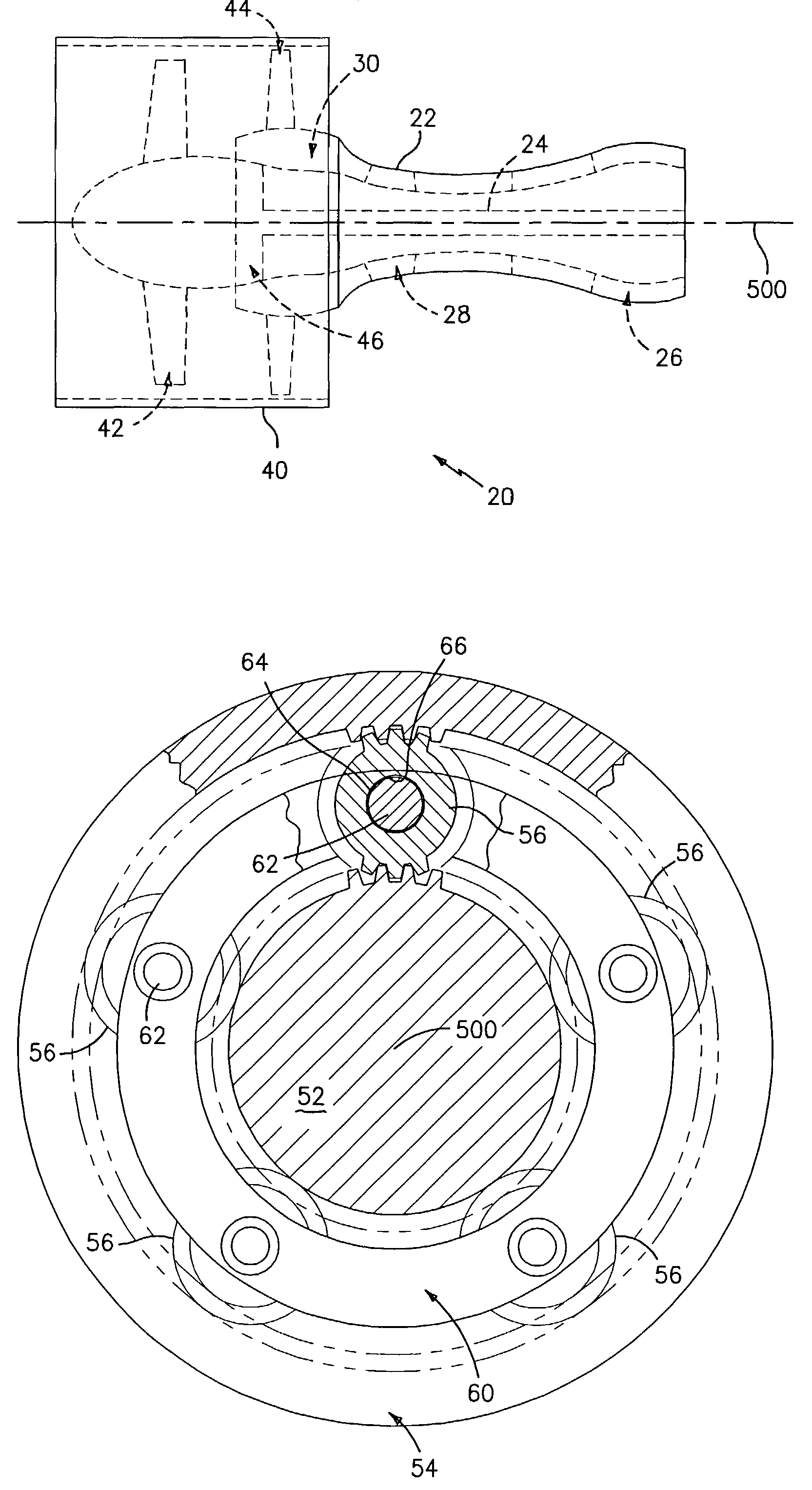
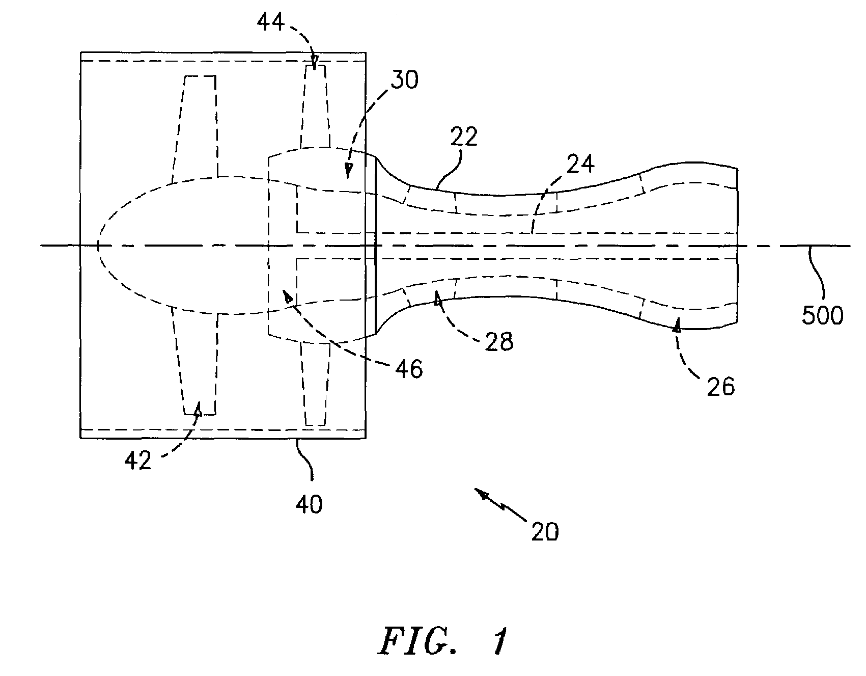
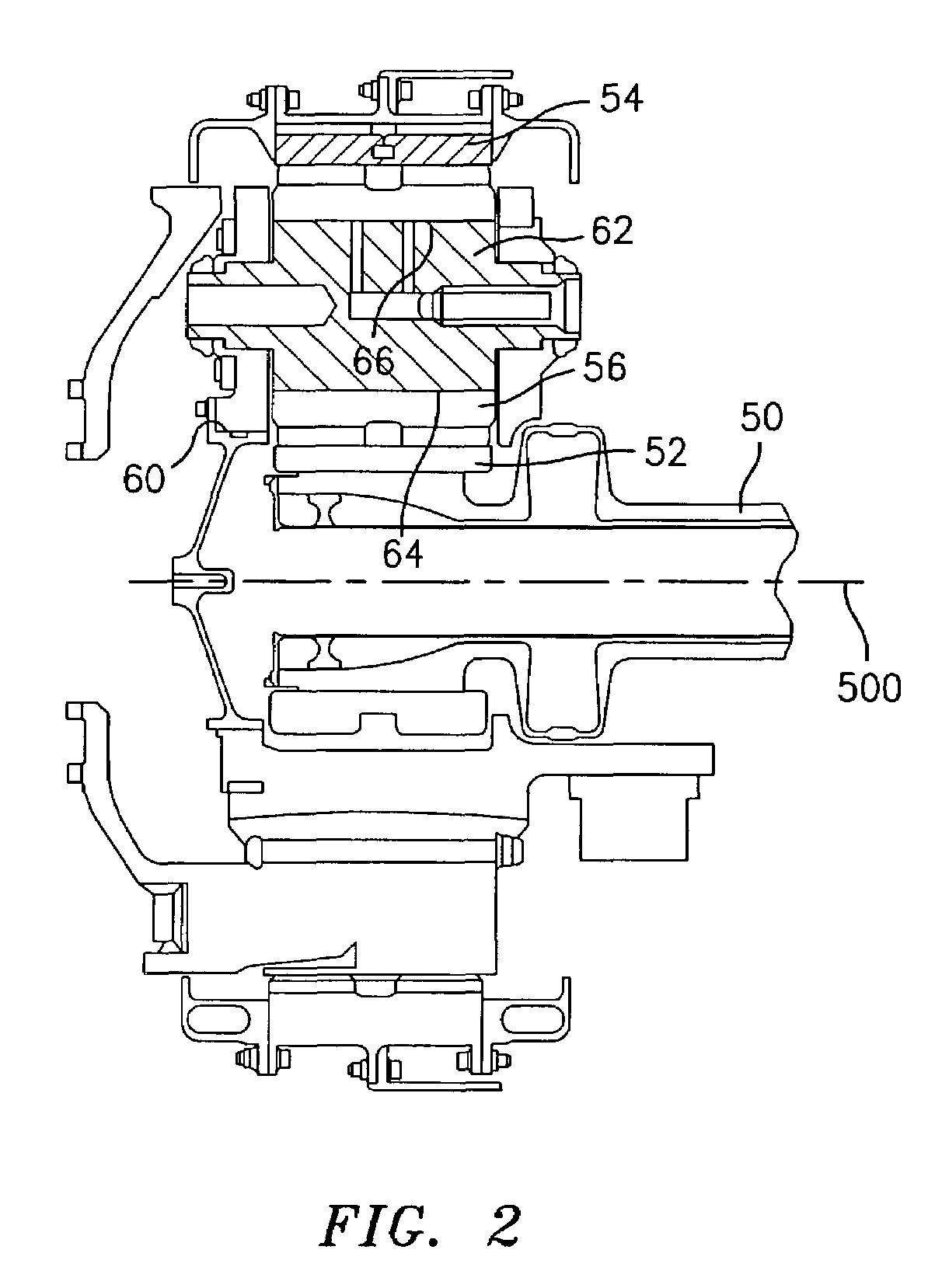
[0014]FIG. 1 shows a geared turbofan engine 20 having a main housing 22 containing a rotor shaft assembly 24. An exemplary engine is a high-bypass turbofan. In such an engine, the normal cruise condition ratio of air mass flowing outside the core (e.g., the compressor sections and combustor) to air mass passing through the core (the bypass ratio) is typically in excess of 4.0 and, more narrowly, typically between 4.0 and 8.0. Via the shaft 24, a turbine section 26 drives high and low pressure compressor sections 28 and 30. The engine extends along a longitudinal axis 500 from a fore end to an aft end. Adjacent the fore end, a shroud 40 encircles a fan 42 and is supported by vanes 44. The rotor shaft assembly 24 drives the fan 42 through a reduction transmission 46. An exemplary reduction transmission is a planetary gear system. FIG. 2 shows further details of the transmission 46. A flexible input shaft 50 at a forward end of the rotor shaft assembly 24 is secured to a sun gear 52. T...


PUM

PropertyMeasurementUnit
thicknessaaaaaaaaaa
thicknessaaaaaaaaaa
thicknessaaaaaaaaaa

Abstract

Molybdenum disulfide (MoS2) is used as a journal coating for a gearing system. A particular application is the planetary gear system of a geared turbofan engine. Particularly advantageous coatings are deposited via physical vapor deposition (PVD) techniques.

Description

BACKGROUND OF THE INVENTION[0001](1) Field of the Invention[0002]This invention relates to turbomachinery, and more particularly to geared turbofan engines.[0003](2) Description of the Related Art[0004]In high bypass turbofan engines it is advantageous that the turbine drive the fan through a reduction gearing system. This permits the turbine to operate at the relatively high speeds at which it is efficient while the much larger diameter fan operates at the relatively lower speeds at which it is efficient. One possible gearing system is a planetary system. In exemplary implementation, the turbine shaft directly drives a sun gear. A number of planet gears are enmeshed between the sun gear and a ring gear that is non-rotating relative to an engine nacelle or other environmental structure in which the turbofan is mounted. The fan is directly driven by a cage holding the planet gears. Bearings are typically provided: (a) for supporting the turbine shaft and sun gear relative to the envi...

Claims


Application Information

Patent Timeline
Patent Type & Authority Patents(United States)
IPC IPC(8): F02K3/02C23C14/06C23C30/00F02C7/36F16H57/04
CPCC23C14/0623C23C30/00F02C7/36F16H57/041Y10S384/913F05D2220/36F05D2260/40311F05D2230/313
Inventor LAW, CHI
Owner RAYTHEON TECH CORP
Why Eureka
Try Eureka