
Rope light having a multi-circuit arrangement

a multi-circuit arrangement, rope light technology, applied in the field of rope light, can solve the problems of increasing manufacturing cost, affecting the performance of rope light, so as to achieve the effect of simple circuit arrangement, reducing the number of rope light elements, and eliminating the diod

Inactive Publication Date: 2006-04-04
HAYASHIBARA BIOCHEMICAL LAB INC
View PDF7 Cites 40 Cited by
  • Summary
  • Abstract
  • Description
  • Claims
  • Application Information

AI Technical Summary

Benefits of technology

[0010]It is an object of the present invention to provide a rope light having a multi-circuit arrangement. By utilizing the rope light, advantages such as elimination of diodes, simple circuit arrangement, saving of electrical wires, compactness, control the lightening sequence of illuminating units, and reduction of manufacturing cost can be obtained.
[0012]It is a further object of the present invention to provide a rope light in which an illuminating unit thereof is implemented as a plate-shaped LED or COB (chip on board) type LED which is fixed on a circuit board by soldering extended conductive wires on the circuit board. By utilizing the rope light, benefits such as improvement of electrical connection to LEDs, increase of stress withstanding capability, simplification of circuit arrangement, significant saving of electrical wires, lightweight, and compactness can be obtained.

Problems solved by technology

In an extreme example, six-circuit of the rope light can be turned on / off by means of the controller coupled among seven electrical wires, resulting in a bulkiness of the rope light.
However, the prior art, by incorporating a plurality of diodes, suffered from several disadvantages.
To the worse, it results in an increase in the manufacturing cost, an increase of size, and a limitation on the number of circuits in the rope light.
Thus, two problems are occurred.
One is that the pins are susceptible of damage in the bending process.
As such, the lamp, as encapsulated by epoxy, tends to malfunction in bending.
Hence, when the electrical wire is wrapped around the pin it is very difficult (or even impossible) of tightly securing them together, though the pins are not damaged by bending.
Such wrapping is not reliable as viewed by an experienced electrical technician.
However, the technique of mounting the socket in the pins has disadvantages of being tedious, time consuming, and cost ineffective, though it is applicable.
However, in view of the accompanying drawings of the prior art, such coupled LEDs may be too large to mount in the rope light, though it is applicable in view of FIG. 3.
Hence, a bending of the LED will cause a short circuit in the exposed portion of the pin.
But, there is no disclosure about how to avoid the use of diode and stress exerted on the pins and the rope light.

Method used


Image

  • Rope light having a multi-circuit arrangement
  • Rope light having a multi-circuit arrangement
  • Rope light having a multi-circuit arrangement

Examples


Embodiment Construction

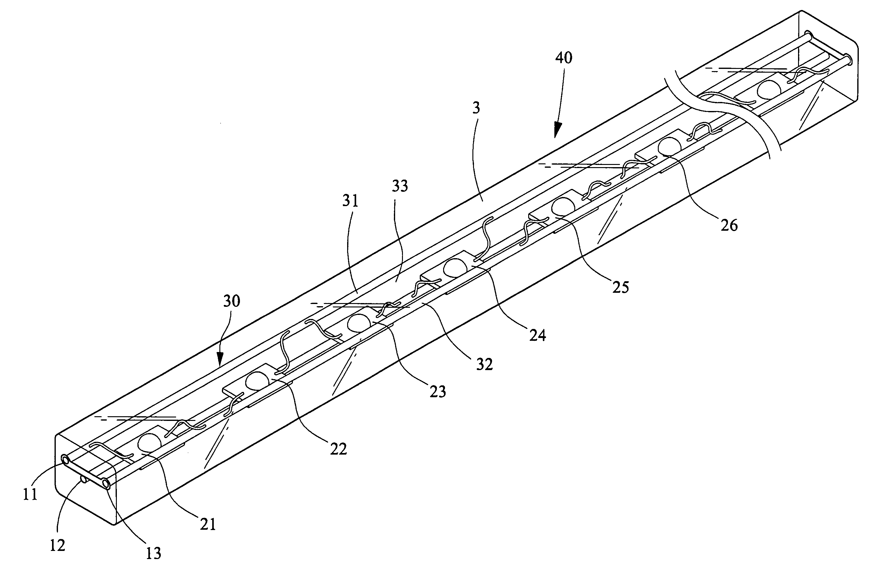
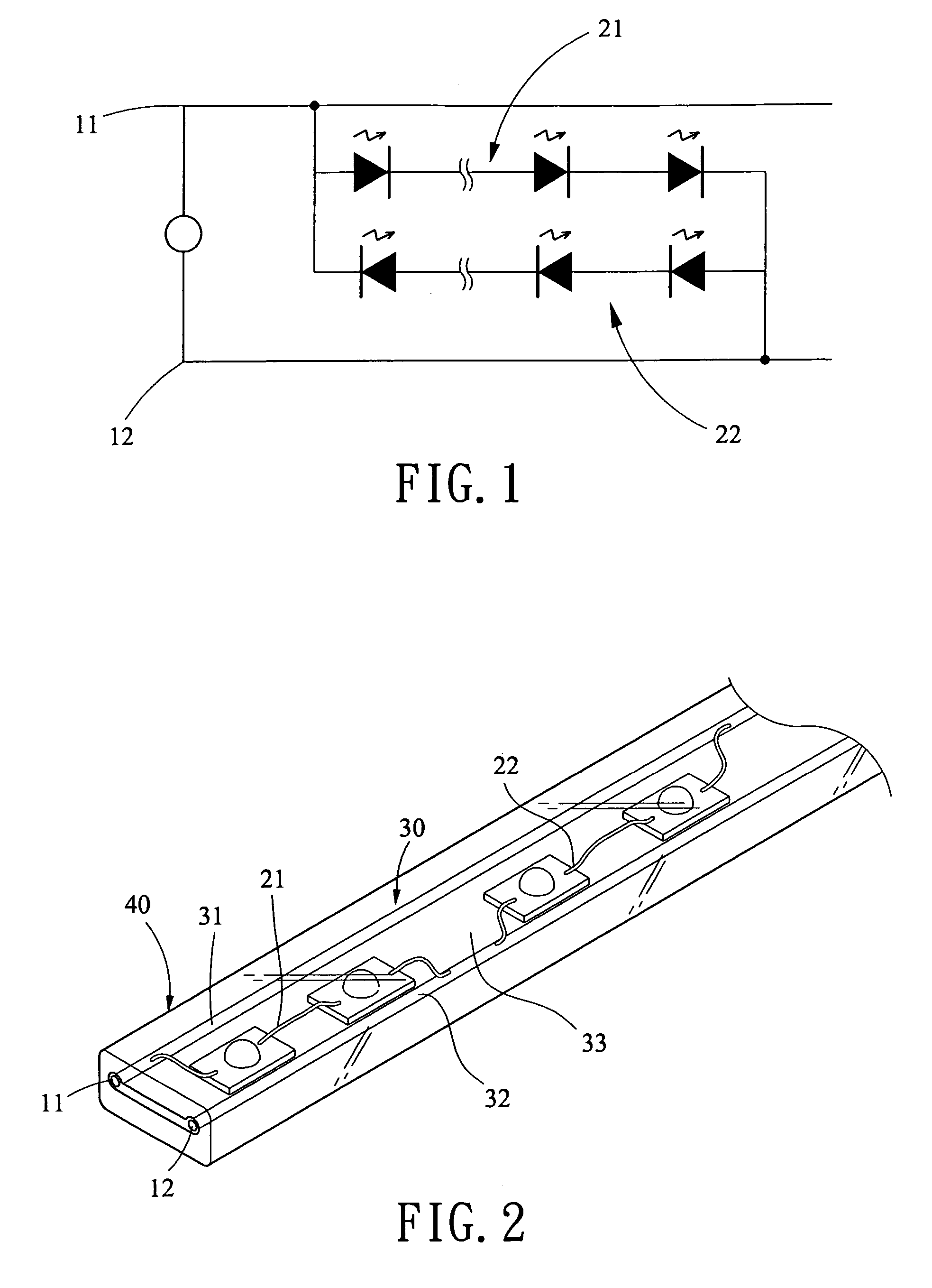
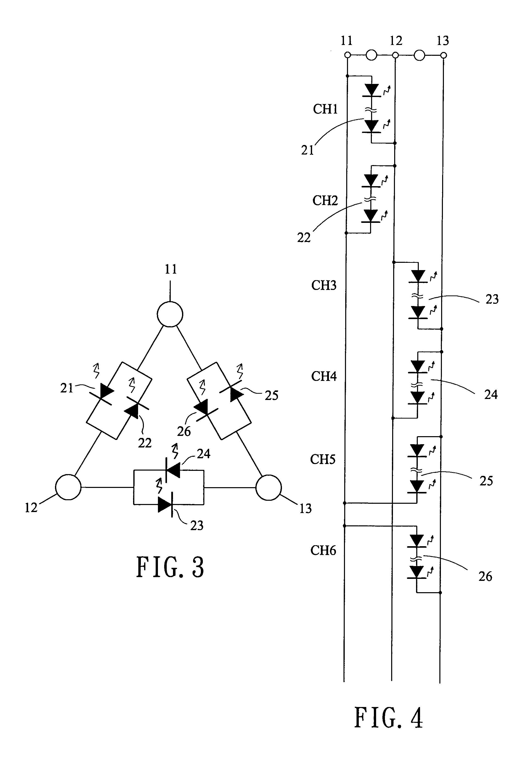
[0023]The invention is directed to a rope light having a multi-circuit arrangement. The invention is devised by distinguishing itself from the narrow prior art after considerable research and experimentation. Also, the inventor adopts the most advanced semiconductor manufacturing technology and fully understands the properties of LED. The rope light of the invention is characterized as follows: No provision of diodes. Instead, the illuminators are implemented as LEDs which are served as both illuminating devices and diodes. As such, component cost of the rope light is greatly reduced due to, as stated above, the elimination of diodes. Also, the manufacturing process is shortened in time and the manufacturing cost is reduced. The LED is implemented as a plate-shaped LED, COB type LED, SMD (surface mounting) LED, or LED dice bonding which is again fixed on a circuit board by soldering extended conductive wires on the circuit board. As such, benefits such as facilitation of the manufac...


PUM


Abstract

A rope light having a multi-circuit arrangement is disclosed. The light comprises a plurality of electrical wires longitudinally extended therealong; and one or more pairs of first and second illuminating units, each pair being electrically coupled between any two electrical wires, each illuminating unit including a plurality of LEDs coupled in series, and the first and the second illuminating units in each pair being connected in parallel. Applying AC source between any two electrical wires sequentially will lighten up the first and the second illuminating units in each pair alternately by enabling current to flow through the LEDs in each illuminating unit toward a predetermined direction when the LEDs are conducted. The invention can control on / off of a plurality of LEDs by means of a relative small number of electrical wires.

Description

BACKGROUND OF THE INVENTION[0001]1. Field of the Invention[0002]The present invention relates to rope light and more particularly to such a rope light having a multi-circuit arrangement with improved characteristics.[0003]2. Description of Related Art[0004]Conventionally, lamps on a single-circuit of a rope light can be turned on / off by means of a controller coupled between two electrical wires. Also, lamps on a double-circuit of the rope light can be turned on / off by means of the controller coupled among three electrical wires (i.e., increase of an additional electrical wire). Likewise, three-circuit of the rope light can be turned on / off by means of the controller coupled among four electrical wires, etc. In an extreme example, six-circuit of the rope light can be turned on / off by means of the controller coupled among seven electrical wires, resulting in a bulkiness of the rope light.[0005]In U.S. Pat. Nos. 6,406,166, 6,527,412, and 6,502,955 there are disclosed a chasing rope lig...

Claims


Application Information

Patent Timeline
Patent Type & Authority Patents(United States)
IPC IPC(8): F21S13/14F21S4/00
CPCF21S4/007F21Y2101/02F21S4/26F21Y2115/10
Inventor LIN, YUAN
Owner HAYASHIBARA BIOCHEMICAL LAB INC
Learn More