
Alignment device for modular implants and method

a modular, implant technology, applied in the field of orthopaedics, can solve the problems of inability to stabilize the joint, difficult to combine all these biomechanic options, and particularly difficult to disloca

Inactive Publication Date: 2006-04-04
DEPUY PROD INC
View PDF92 Cites 103 Cited by
  • Summary
  • Abstract
  • Description
  • Claims
  • Application Information

AI Technical Summary

Benefits of technology

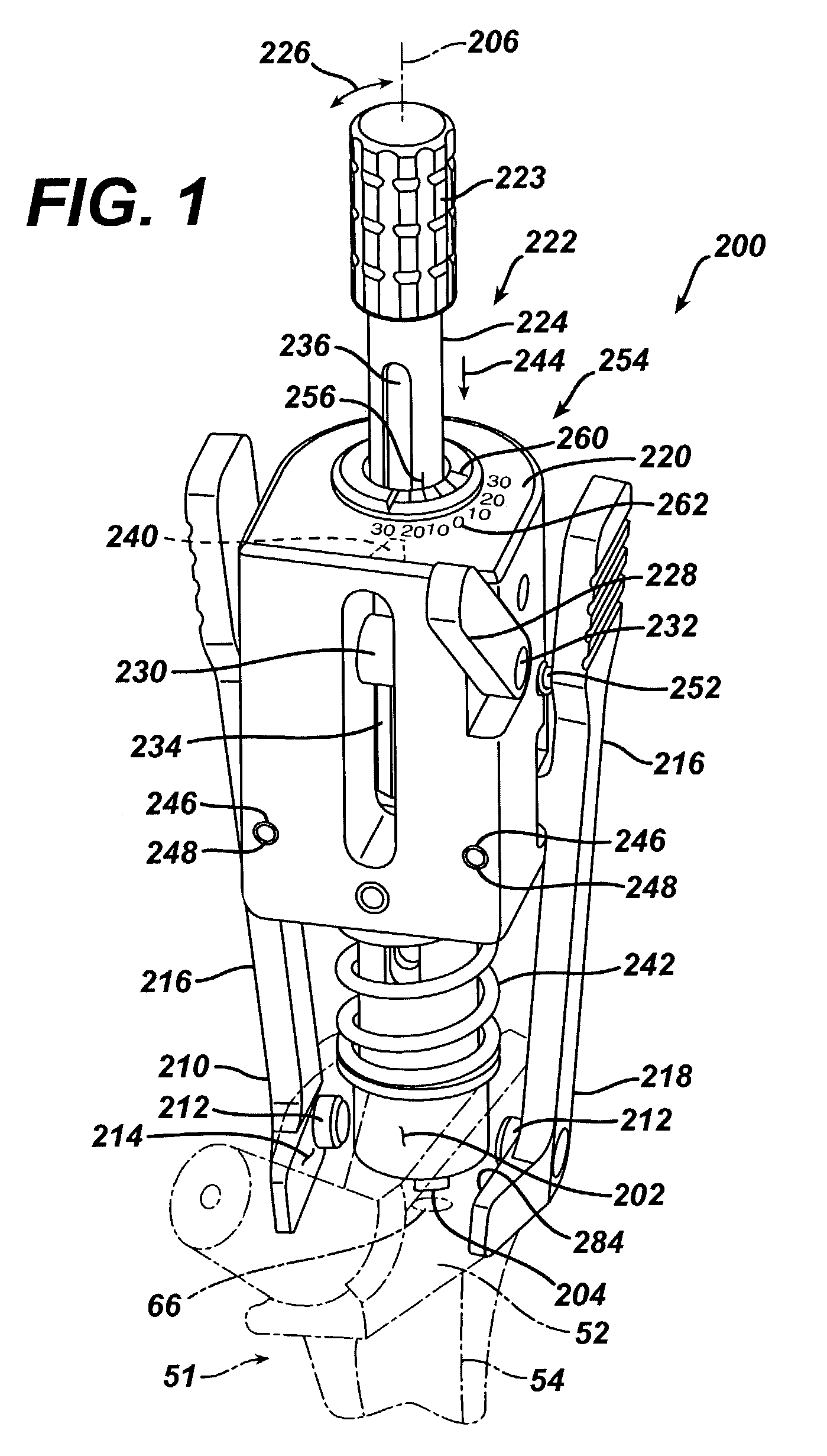
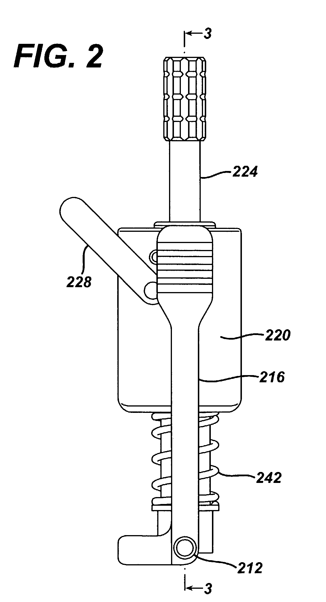
[0021]Another technical advantage of the present invention includes the ability of the current invention to be used on the back table outside the body and in location in the patient's bone. For example, according to one aspect of the present invention, the angular orientation feature of the distal stem, as well as the angular orientation feature of the proximal body and neck, are both accessible and utilized with the instrument in a position accessible to the surgeon while the implant is in position in the bone. Thus, the present invention provides for use on the back table and in the bone.
[0022]Another technical advantage of the present invention includes the ability of the instrument of the present invention to be used on trial components and on implants. For example, according to one aspect of the present invention, the angular orientation feature for the bowed distal stem for both an implant and a trial is located proximally so that the instrument of the present invention can locate the angular orientation of the bowed distal stem on either a trial or an implant. Similarly, the proximal body and neck implant and the proximal body and neck trial are designed with angular orientation features that cooperate with the instrument of the present invention, which may be located proximally on the implant and trial. The surgeon can thus use a distal stem trial and proximal body trial to intraoperatively set anteversion and then replicate it in the modular implant. Similarly, the surgeon can use a distal stem implant and a proximal body trial to intraoperatively set anteversion and then replace the proximal body trial with a proximal body implant leaving the distal stem implant in the patient's femur. Thus, the present invention provides for use of the orientation device on both trial components and on implants.
[0023]Another technical advantage of the present invention includes the ability of the proposed instrument to control the rotational alignment of the distal stem independently of the neck of the component. For example, according to one aspect of the present invention, the alignment device includes a feature for cooperation with an orientation feature for a bowed distal stem as well as an orientation feature for a proximal body. Thus, the present invention provides for rotational alignment of a distal stem independent of the neck of the component.
[0024]Another technical advantage of the present invention includes the ability to use CT measurement data or a predetermined version angle predetermined by any other method determined by the physician and reproduce the predetermined version angle. For example, according to one aspect of the present invention, the instrument includes indication or marks on the instrument corresponding to various predetermined version angles. Thus, the present invention provides for orienting the implant or trial at a predetermined version angle.
[0025]In primary hip surgery, many of the bony landmarks are obscured by osteophyte formation, post-traumatic deformities, bone loss, etc. The one true landmark that is always present is the intramedullary canal. In a revision surgery, the anatomy is typically more severely affected and the standard referencing landmarks may no longer be available or are compromised. Hence, this instrument allows the surgeon to find, measure and optimize an anteversion relative to the anteriorly bowed intramedullary canal. This bowed canal is always present and is independent of excess tissue, poor x-ray techniques, proximal bone loss, patient positioning on the table, certain proximal deformities such as DDH, neck fractures, and so forth. In fact, it is one part of the anatomy that the surgeon almost always has available to use in extremely difficult cases.

Problems solved by technology

Currently, in total hip arthroplasty, a major critical concern is the instability of the joint.
Dislocation is particularly a problem in total hip arthroplasty.
The combination of all these biomechanic options is rather complex.
Improper version can lead to dislocation and patient dissatisfaction.
However, it becomes a more challenging issue with the advent of stems with additional modularity.
Therefore, the anteversion is limited.
For example, at an anteversion of 15°, these monolithic stems have limited flexibility for rotational alignment since the distal stem must follow the bow of the patient's femur and this may not provide an optimal biomechanical result.

Method used


Image

  • Alignment device for modular implants and method
  • Alignment device for modular implants and method
  • Alignment device for modular implants and method

Examples


Embodiment Construction

[0061]Embodiments of the present invention and the advantages thereof are best understood by referring to the following descriptions and drawings, wherein like numerals are used for like and corresponding parts of the drawings.

[0062]Referring now to FIGS. 16 and 19, a hip stem 10 is shown. The hip stem 10 is suitable for use with the alignment instrument of the present invention. The hip stem 10 may be made of any suitable durable material which is compatible with the human body. For example, the hip stem 10 may be made of a titanium alloy, a cobalt chromium alloy, or a stainless steel alloy. As shown in FIGS. 16 through 19, the hip stem 10 includes a proximal body 12 and a bowed distal stem 14.

[0063]Referring now to FIG. 18, the proximal body 12 may be secured to the distal stem 14 in any suitable fashion. For example and as shown in FIG. 18, the proximal body 12 may be secured to the distal stem 14 by means of threads 15 located on the proximal portion of the proximal body 12 whic...


PUM


Abstract

An instrument (200) for at least one of replicating and measuring the angular orientation of a first component (54) of a prosthesis (51) to a second component (52) of the prosthesis (51) for use in joint arthroplasty. The instrument (200) includes a first member (202) for cooperation with the first component (54), a second member (210) for cooperation with the second component (52), and a feature (220). The feature (220) cooperates with the first member (202) and the second member (210) for at least one of replicating and measuring the relative angular orientation of the first component (54) with respect to the second component (52).

Description

CROSS-REFERENCE TO RELATED APPLICATIONS[0001]Cross reference is made to the following applications: DEP 644 entitled “ADJUSTABLE BIOMECHANICAL TEMPLATING & RESECTION INSTRUMENT AND ASSOCIATED METHOD”, DEP 725 entitled “INSTRUMENT AND ASSOCIATED METHOD OF TRIALING FOR MODULAR HIP STEMS” and DEP 5004 entitled “MODULAR HIP STEMS AND ASSOCIATED METHOD OF TRIALING” filed concurrently herewith which are incorporated herein by reference.TECHNICAL FIELD OF THE INVENTION[0002]The present invention relates generally to the field of orthopaedics, and more particularly, to an implant for use in arthroplasty.BACKGROUND OF THE INVENTION[0003]Patients who suffer from the pain and immobility caused by osteoarthritis and rheumatoid arthritis have an option of joint replacement surgery. Joint replacement surgery is quite common and enables many individuals to function properly when it would not be possible otherwise to do so. Artificial joints usually comprise metal, ceramic and / or plastic components...

Claims


Application Information

Patent Timeline
Patent Type & Authority Patents(United States)
IPC IPC(8): A61F2/32A61B19/00A61F2/00A61F2/30A61F2/36A61F2/46A61F2/48A61F2/76
CPCA61F2/4657A61F2/36A61B2019/467A61F2002/4687A61F2/367A61F2/3676A61F2002/30332A61F2002/30438A61F2002/3054A61F2002/30604A61F2002/30738A61F2002/30827A61F2002/30886A61F2002/3611A61F2002/3625A61F2002/365A61F2002/3656A61F2002/3674A61F2002/3686A61F2002/3696A61F2002/4668A61F2220/0033A61F2220/0041A61B2090/067A61F2002/30433A61F2002/30594
Inventor DWYER, KIMBERLY A.DANIELS, DAVIDPARKER, BRAD
Owner DEPUY PROD INC
Learn More