Aerobic wastewater management system, apparatus, and method
a wastewater management system and aerobic technology, applied in the direction of multi-stage water/sewage treatment, liquid displacement, separation process, etc., to achieve the effect of reducing waste, digesting waste, and increasing the efficiency and performance of the overall uni
- Summary
- Abstract
- Description
- Claims
- Application Information
AI Technical Summary
Benefits of technology
Problems solved by technology
Method used
Image
Examples
first embodiment
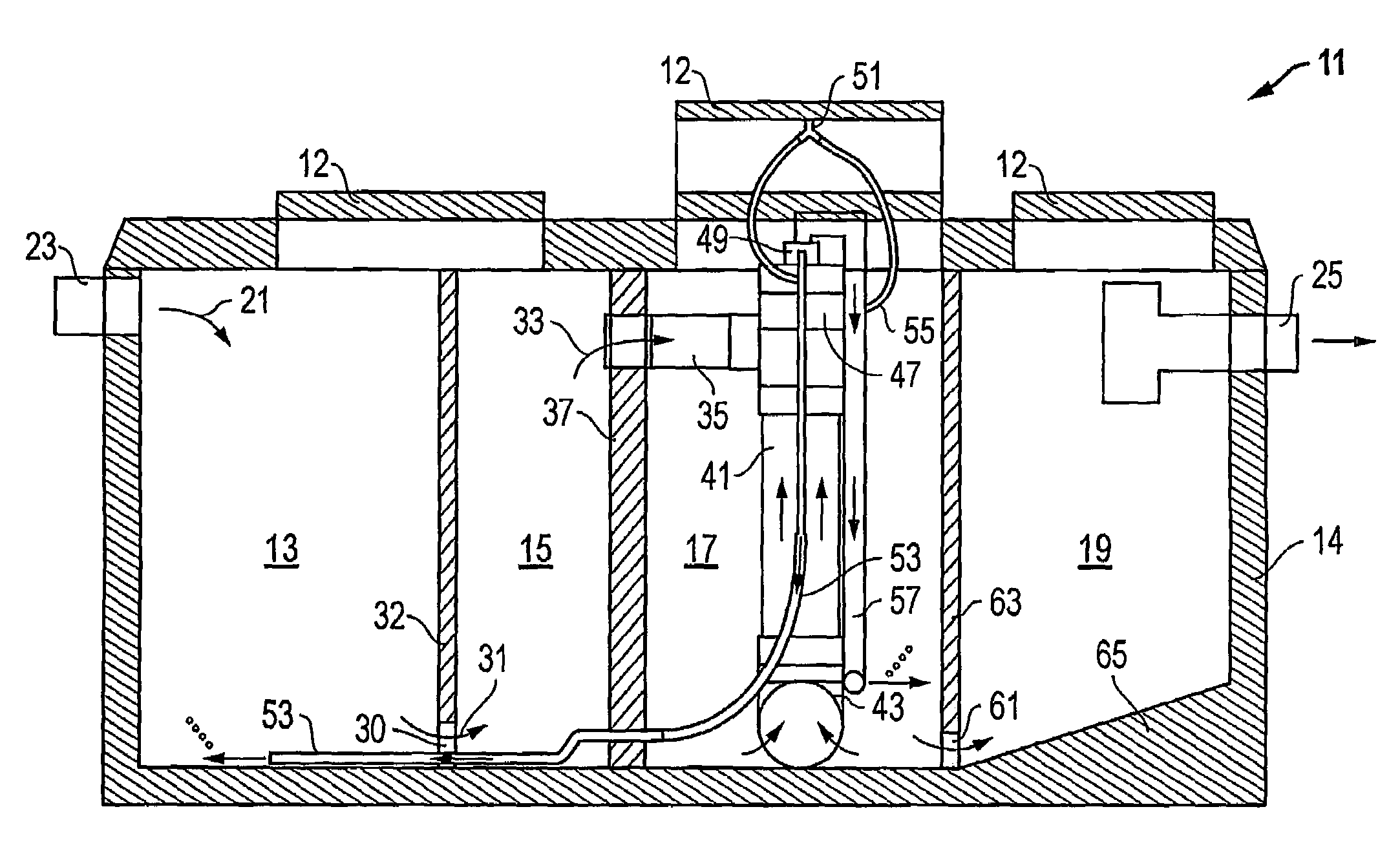
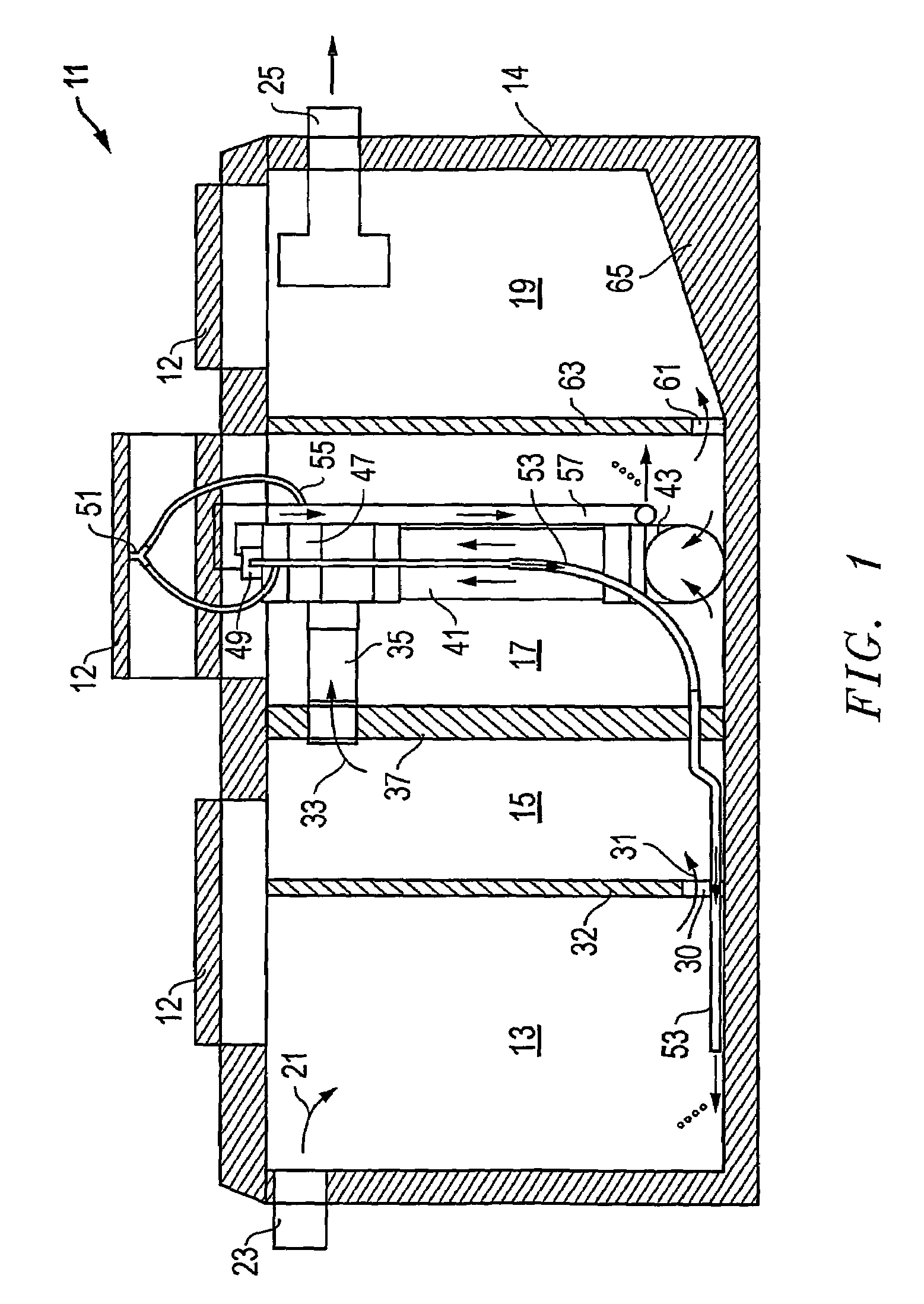
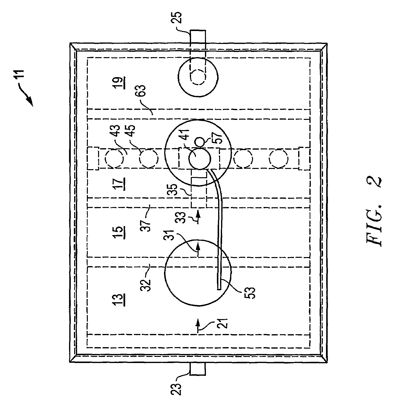
[0022]Referring to FIGS. 1 and 2, an aerobic wastewater management system 11 constructed in accordance with the present invention is shown. System 11 comprises a generally rectangular tank 14 (e.g., a septic tank) having four side walls, a bottom, and a top with resealable access ports 12. The tank 14 also has four compartments 13, 15, 17, 19, and each compartment is separated by partitions that are located within tank 14. Wastewater or sewage, indicated by arrow 21, enters system 11 at entry port 23 in a conventional manner and generally flows left to right as it is processed and bio-nutrients are removed, until reclaimed water is produced and exits system 11 at exit port 25. The discharge is then distributed in a conventional manner.
[0023]As wastewater 21 enters system 11 via attached plumbing (not shown), it contains both organic matter and human waste, which is also known as effluent. The effluent is deposited through entry port 23 directly into the first compartment, or trash t...
second embodiment
[0031]Referring now to FIG. 3, an aerobic wastewater management system 111 constructed in accordance with the present invention is shown. System 111 is very similar to the previously described system 11, except for two variations: system 111 does not have a spin filter, and there is no aeration in trash tank 113. Instead, system 111 blends air into the unfiltrated liquid and suspended solids via a single air intake device 155 wherein they are thoroughly blended with air that has been drawn from the ambient atmosphere outside of system 111. No portion of this blended mixture of suspended solids, liquid, and air, also known as aerated precipitate, is discharged into the trash tank 113. Instead, all of the aerated precipitate is discharged back into the mix liquor compartment 117 through a tube 157. The introduction of air into compartment 17 via tube 57 facilitates the growth of aerobic bacteria that digest organic material, which virtually eliminates the presence of sludge in compart...
third embodiment
[0032]Referring now to FIG. 4, an aerobic wastewater management system 211 constructed in accordance with the present invention is shown. System 211 is most similar to the previously described system 11, except for one variation: system 211 does not have a first settling compartment between its trash tank 213 and its mix liquor compartment 217. Instead, system 211 draws effluent directly from trash tank 213, via an elongated tube 235 with a vertical conduit extending from the lower end of trash tank 213, directly into pipe 241 and pump 247. The other elements of system 211, including the pumping, circulation, aeration, and discharge, work in the same manner as those described above for system 11.
PUM
| Property | Measurement | Unit |
|---|---|---|
| height | aaaaa | aaaaa |
| depth | aaaaa | aaaaa |
| depth | aaaaa | aaaaa |
Abstract
Description
Claims
Application Information
 - R&D
- Intellectual Property
- Life Sciences
- Materials
- Tech Scout
- Unparalleled Data Quality
- Higher Quality Content
- 60% Fewer Hallucinations
Browse by: Latest US Patents, China's latest patents, Technical Efficacy Thesaurus, Application Domain, Technology Topic, Popular Technical Reports.
© 2025 PatSnap. All rights reserved.Legal|Privacy policy|Modern Slavery Act Transparency Statement|Sitemap|About US| Contact US: help@patsnap.com


