Method in connection with the production of a template and the template thus produced

a technology of template and template, which is applied in the field of template production, can solve the problems of difficult to achieve an adequate and even voltage distribution, difficult to produce very small structures, and many steps, and achieve the effects of low cost, small size and simple production process

Inactive Publication Date: 2006-04-04
OBDUCAT AB SE
View PDF13 Cites 25 Cited by
  • Summary
  • Abstract
  • Description
  • Claims
  • Application Information

AI Technical Summary

Benefits of technology

[0013]The present invention aims at solving the above complex of problems and at presenting a method in connection with the production of a template, preferably for nanoimprint lithography, which method is simple, cheap and repetitive and which yields durable structures of small size and with a beneficial profile for a subsequent imprint step.

Problems solved by technology

The problem of the method is however that it comprises many steps, having many parameters that have to be tuned in.
Furthermore, it is often hard to achieve an adequately even voltage distribution in the plating and moreover, it is not possible to produce very small structures, which is ever more required following the development in the field.
A problem which quite often arises thereby is that the etching also acts in a lateral direction to a certain degree, causing that the metal material forms a “hat” that somewhat protrudes outside every separate element of the structure.
This “hat” risks to get caught in the polymeric material on the substrate in connection with imprint step no.
2 according to the above, which results in an unacceptable result of the imprint.
Up to now, it has not been possible to use a template where the three-dimensional structure only consists of a metal material which is applied according to the first steps in the etching method just described, i.e. the steps up to and including the lift-off process.
Accordingly, parts of the structure come loose from the plate whereby the template soon becomes useless for its purpose.

Method used


Image

  • Method in connection with the production of a template and the template thus produced
  • Method in connection with the production of a template and the template thus produced
  • Method in connection with the production of a template and the template thus produced

Examples


first embodiment

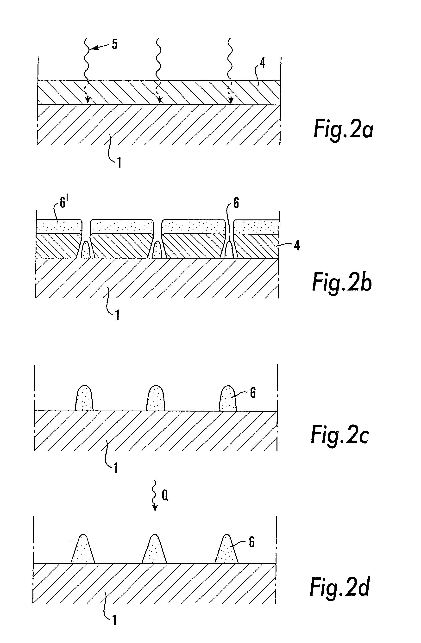
[0019]FIGS. 2a–d is showing, in cross-section, the process steps for the production of a template according to the invention,

second embodiment

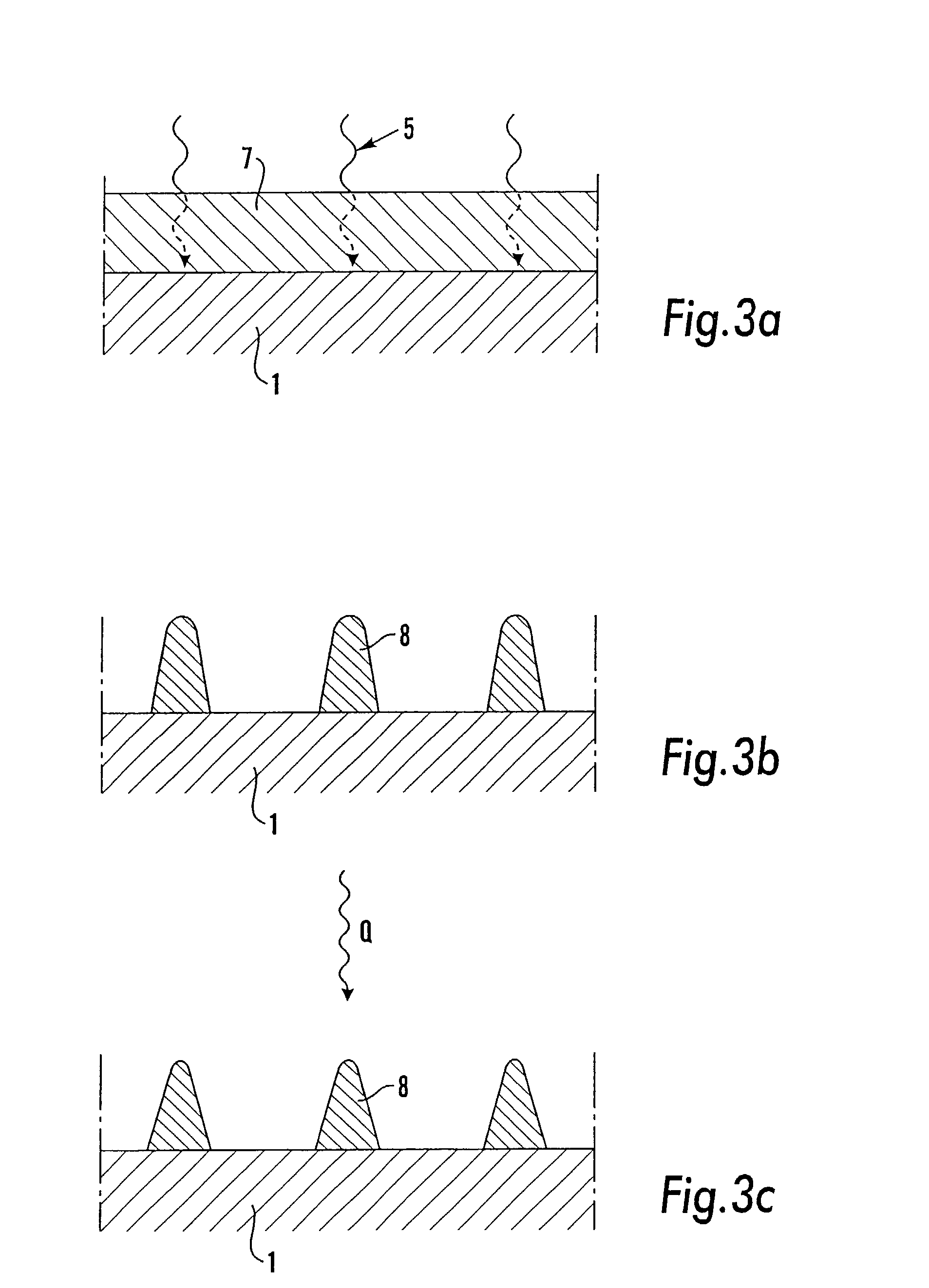
[0020]FIGS. 3a–c is showing, in cross-section, the process steps for the production of a template according to the invention,

[0021]FIGS. 4a–c is showing, in cross-section and a light perspective, SEM pictures of three different templates which have been produced according to the invention.

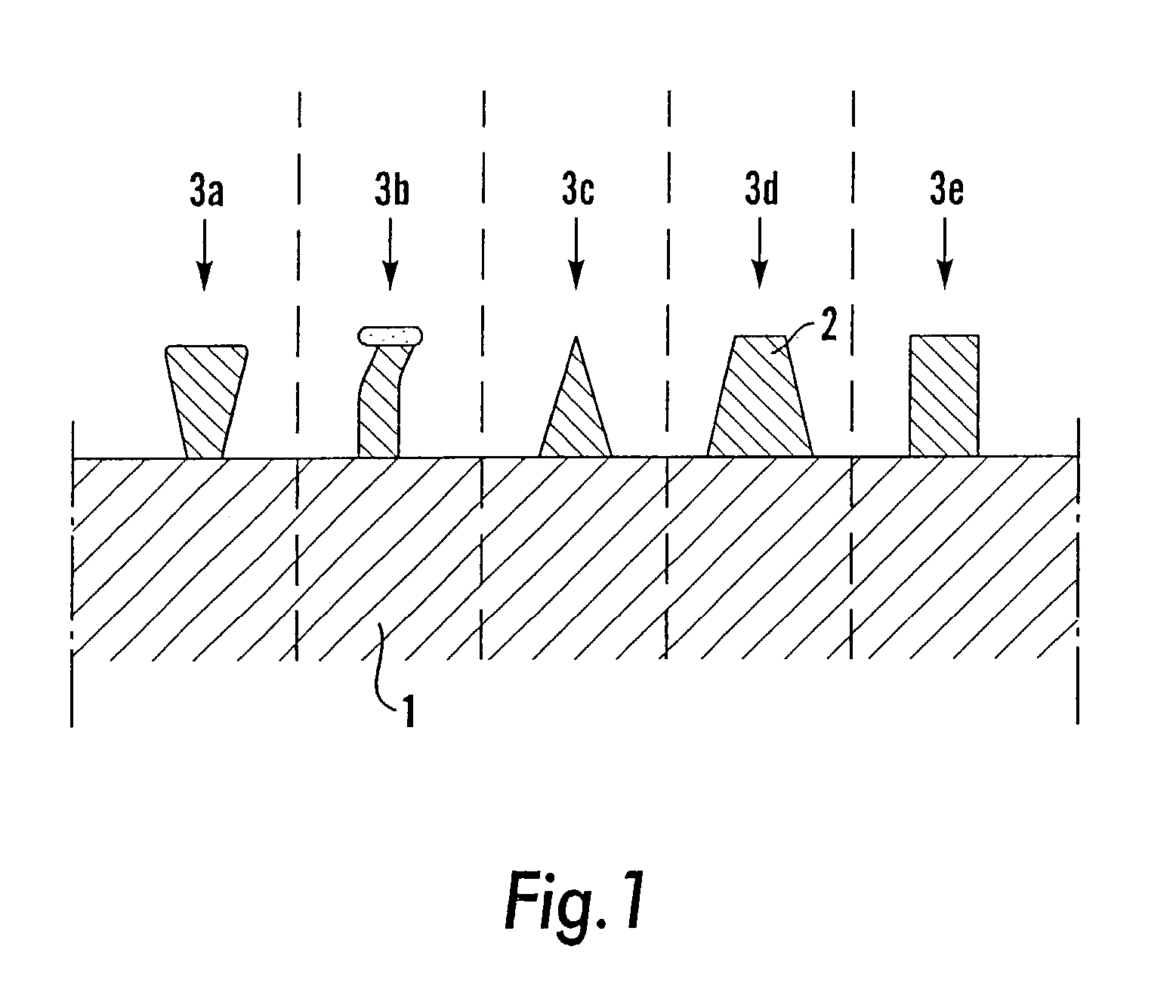
[0022]In FIG. 1 there is shown, in cross-section, a number of different structural details which may be produced on a template, according to known technique. On a plate 1, there has been produced different imagined structural details 3a–e, of a material 2. Detail no. 3a exhibits a non-beneficial profile, which after imprint in a resist that has been softened by heating and solidified by cooling, on a not shown substrate, risks to get caught in the resist on the substrate. This is also the case for structural detail no. 3b, which has been produced by etching according to the description above of known techniques, and which exhibits a protruding “hat”. The structural details 3c, 3d and possibly even ...


PUM

PropertyMeasurementUnit
temperatureaaaaaaaaaa

Abstract

Method in connection with the production of a template, preferably for nanoimprint lithography, which template comprises a flat plate (1) of a first material and a three-dimensional structure (6, 8) of a second material, arranged on the plate, said second material introductory being applied on said plate, in the method, to form the structure. The second material is thereafter fixed to the plate the second material is thereafter fixed to the plate of the first material, by heat treatment (Q) at at least 100° C., for the production of the template. A template is produced by use of the method.

Description

[0001]This application is the national phase under 35 U.S.C. § 371 of PCT International Application No. PCT / SE01 / 00787 which has an International filing date of Apr. 10, 2001, which designated the United States of America.[0002]1. Technical Field[0003]The present invention relates to a method in connection with the production of a template, which template comprises a flat plate of a first material and a three-dimensional structure of a second material, arranged on the plate, said second material introductory being applied on said plate, in the method, to form said structure. The method has primarily been developed for use in connection with the production of semiconductor components by use of nanoimprint lithography, the template produced according to the method being used as a template in connection with series production of such semiconductor components, but it may also be used in connection with nanoimprint lithography on other rigid materials, such as ceramic materials, metals o...

Claims


Application Information

Patent Timeline
Patent Type & Authority Patents(United States)
IPC IPC(8): G03F7/00G03F7/26B41C1/10B41M1/06G03F7/40G11B7/26H01L21/027
CPCB82Y10/00B82Y40/00G03F7/0017G03F7/0002B41C2210/04G11B7/261
Inventor HEIDARI, BABAK
Owner OBDUCAT AB SE
Why Eureka
Try Eureka