Apparatus and method for a scanning probe microscope

a scanning probe and microscope technology, applied in scanning probe microscopy, nanotechnology, instruments, etc., can solve the problems of vertical measurement error, inability to image the reflected measuring light on the photodiode, and inability to simultaneously correct the lateral tracking of the measuring light rays, so as to facilitate the precise performing of optical microscopic examination, improve the stability of the measuring assembly, and optimize mechanical properties

Inactive Publication Date: 2006-04-04
JPK INSTR
View PDF3 Cites 122 Cited by
  • Summary
  • Abstract
  • Description
  • Claims
  • Application Information

AI Technical Summary

Benefits of technology

[0015]Another advantage of the invention resides in the possibility offered by the condenser light path, namely to examine the specimen microscopically without irradiation by condenser light. To this end, is light for examining the specimen is received microscopically, it spreads from the specimen along the condenser light path to a microscope. A vertical illumination microscope may be used for this kind of optical microscopic examination. Here the condenser light path is utilized as a kind of observation channel which is available also during the scanning probe microscopic examination of the specimen.
[0016]A convenient modification of the invention provides for the condenser light path to be formed substantially centrally through the measuring assembly. Thus it is guaranteed that the components of the measuring assembly may be placed as closely as possible to the condenser light path, which helps render the measuring assembly structure stable and resistent to oscillations.
[0017]In an advantageous embodiment of the invention the condenser light path may be devised so as to pass through the lateral shifting means. In a preferred embodiment of the invention any influence which the lateral shifting means might have on the condenser light path is prevented almost entirely by having the condenser light path extend through an opening in the lateral shifting means. The stability of the measuring assembly is improved in an advantageous embodiment of the invention in that the vertical shifting means is arranged next to the condenser light path.
[0018]A structure having optimized mechanical properties is achieved by a convenient further development of the invention according to which the vertical shifting means comprises a plurality of vertical shifting elements arranged around the condenser light path.
[0019]A convenient further development facilitates precise performing of the optical microscopic examination of a specimen due to the fact that the condenser light path extends substantially parallel to vertical axis. A further development may provide for the condenser light path to extend substantially parallel to the measuring light rays which are directed at the cantilever in the scanning probe microscopic examination.
[0020]A convenient modification of the invention makes sure that the condenser illumination can spread as usual with conventional optical microscopes, with the least possible obstruction, by configuring the condenser light path such that condenser light can spread shaped like a substantially conical condenser light cone towards the specimen support. To achieve that, the structural elements of the scanning probe microscope are designed in a way which enhances the conical spreading of the condenser light.

Problems solved by technology

This kind of implementation is disadvantageous in that it requires various setting means for adjusting the light source which generates the measuring light rays.
Imaging of the reflected measuring light on the photodiode is not possible unless lateral tracking of the measuring light rays is provided, especially when measurements are made which require scanning of large areas by means of the cantilever.
However, this method has the disadvantage that the lateral tracking of the measuring light rays does not permit simultaneous correction of a vertical measuring error which also exists.
A vertical measuring error occurs when the cantilever, rather than being oriented at right angles to the direction of incidence of the measuring light rays, is slightly inclined.
But the implementations described above of the light spot principle with stand-alone scanning probe microscopes do not allow the probe to be examined by means of an optical microscope disposing of condenser illumination when the specimen is positioned on a specimen support (slide) so as to be measured by means of the scanning probe microscope.

Method used


Image

  • Apparatus and method for a scanning probe microscope
  • Apparatus and method for a scanning probe microscope
  • Apparatus and method for a scanning probe microscope

Examples


Embodiment Construction

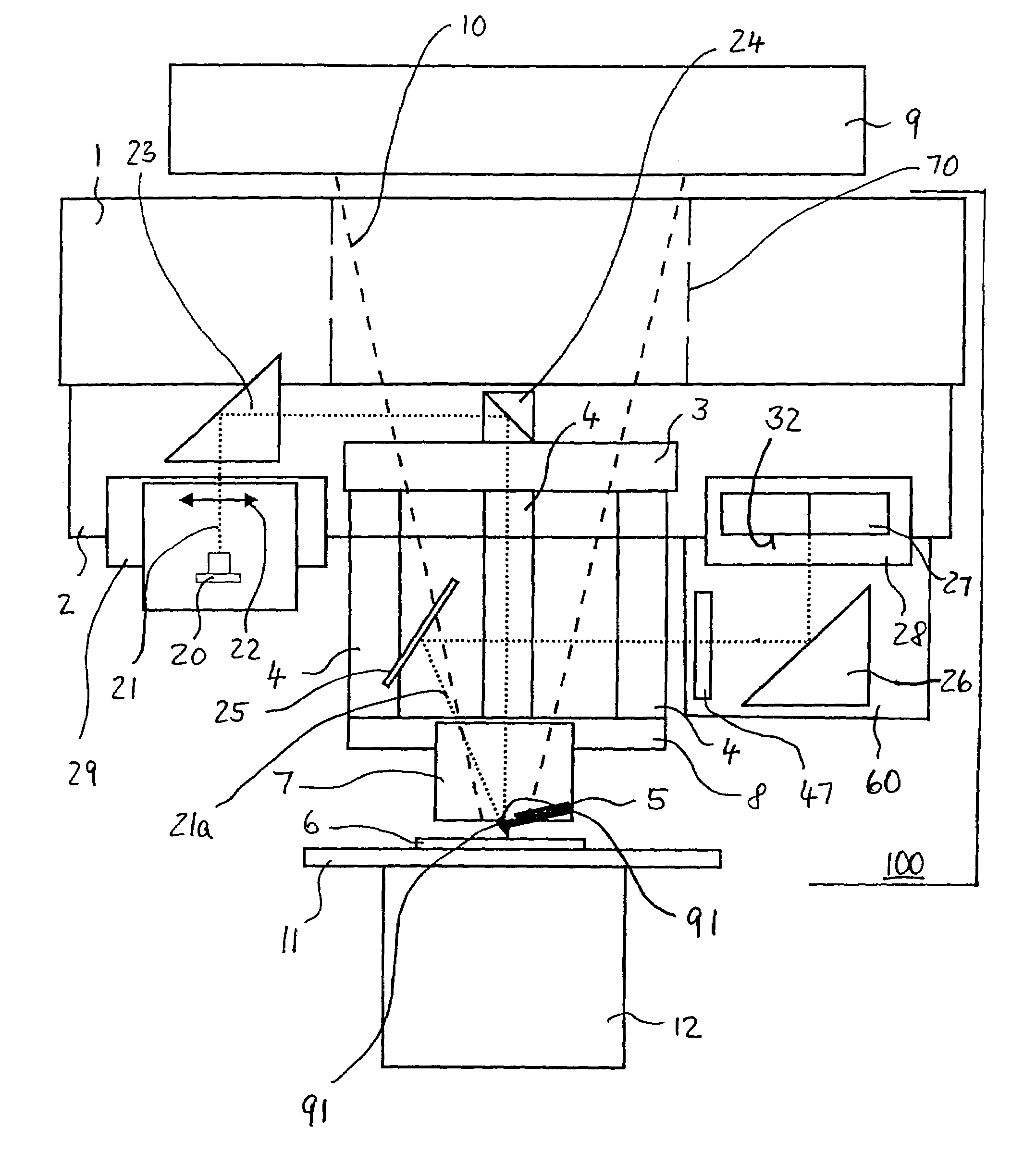
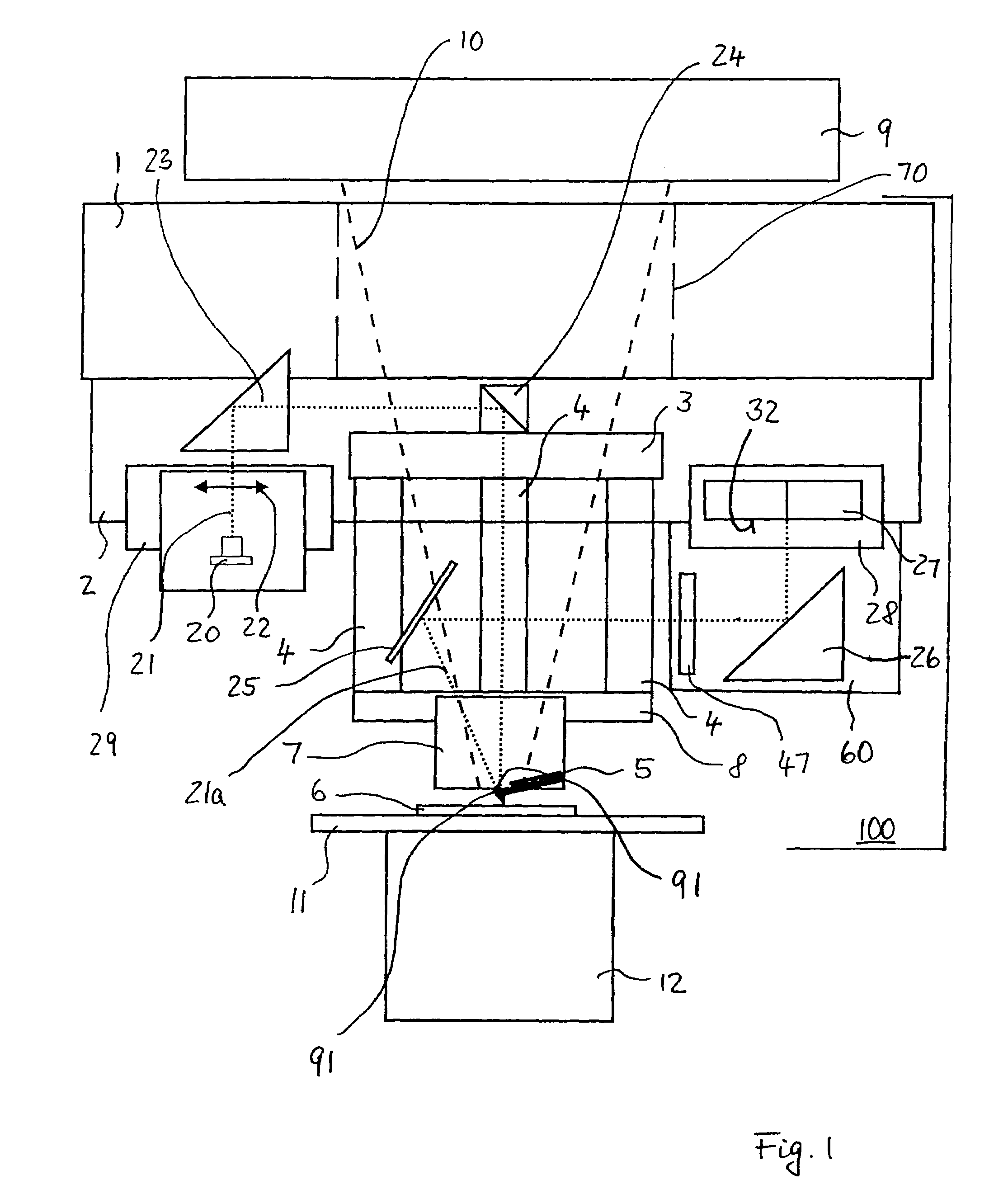
[0032]FIG. 1 diagrammatically shows a measuring assembly 100 for a scanning probe microscope, especially a scanning force microscope, comprising a lateral shifting unit 1 which permits precise movement of the other structural elements connected to the lateral shifting unit 1 in a plane extending vertically to the plane of the drawing in FIG. 1. The lateral shifting unit 1 may be composed, for example, of piezoelectric elements. In principle, however, any desired kind of apparatus may be used as long as they permit accurate displacement in a plane. A frame member 2 is mounted on the lateral shifting unit. Further structural members of the arrangement shown in FIG. 1 for a scanning probe microscope are fastened to the frame member 2 in a way so as to be movable in lateral direction with the aid of the lateral shifting unit 1.

[0033]A glass plate 3 is retained on the frame member 2. A plurality of vertical shifting units 4, preferably embodied by piezoelectric structural elements are mo...


PUM

PropertyMeasurementUnit
areaaaaaaaaaaa
shapeaaaaaaaaaa
transparentaaaaaaaaaa

Abstract

The invention relates to an apparatus and a method for a scanning probe microscope, comprising a measuring assembly which includes a lateral shifting unit to displace a probe in a plane, a vertical shifting unit to displace the probe in a direction perpendicular to the plane, and a specimen support to receive a specimen. A condenser light path is formed through the measuring assembly so that the specimen support is located in the area of an end of the condenser light path.

Description

[0001]The invention concerns apparatus and methods for scanning probe microscopy (SPM).BACKGROUND OF THE INVENTION[0002]1. Field of the Invention[0003]Scanning force microscopy (SFM) (AFM—atomic force microscopy) is one form of scanning probe microscopy. An important field of application of scanning probe microscopy is the determination of the topography of a specimen surface with high lateral and vertical resolution. The term “lateral resolution” in this context refers to the resolution in a plane of the surface under examination. The direction perpendicular to this plane is called vertical direction. In vertical direction, the topography of the surface is determined by vertical resolution. In addition to the topology, other characteristics of a specimen to be examined can be measured, such as the elasticity or forces of adhesion. Also optical near field microscopes belong to the class of scanning probe microscopes (SNOM—scanning near field optical microscope).[0004]To be able to u...

Claims


Application Information

Patent Timeline
Patent Type & Authority Patents(United States)
IPC IPC(8): G01N23/00G01B21/00G01B21/30G01Q20/02G01Q60/06
CPCB82Y35/00G01Q20/02Y10S977/868
Inventor KNEBEL, DETLEFJAHNKE, TORSTENSUNWOLDT, OLAF
Owner JPK INSTR
Why Eureka
Try Eureka