Oven controlled crystal oscillator for high stability

a crystal oscillator and high stability technology, which is applied in the direction of instruments, domestic cooling apparatus, optical radiation measurement, etc., can solve the problems of decreasing manufacturing costs, achieve the effect of preventing momentary fluctuations in the oscillating frequency of the crystal oscillator, improving the operation of the close contact with the flexible material, and improving the heat capacity of the thermosta

Inactive Publication Date: 2006-04-04
NIHON DEMPA KOGYO CO LTD
View PDF5 Cites 22 Cited by
  • Summary
  • Abstract
  • Description
  • Claims
  • Application Information

AI Technical Summary

Benefits of technology

[0015]An object of the present invention is to provide a highly stable oscillator having increased thermal efficiency.

Problems solved by technology

Furthermore, since the chip resistor is used as the heat source, then for example, the coiling operation for the heating coil becomes unnecessary, thus decreasing manufacturing costs.

Method used


Image

  • Oven controlled crystal oscillator for high stability
  • Oven controlled crystal oscillator for high stability
  • Oven controlled crystal oscillator for high stability

Examples


first embodiment

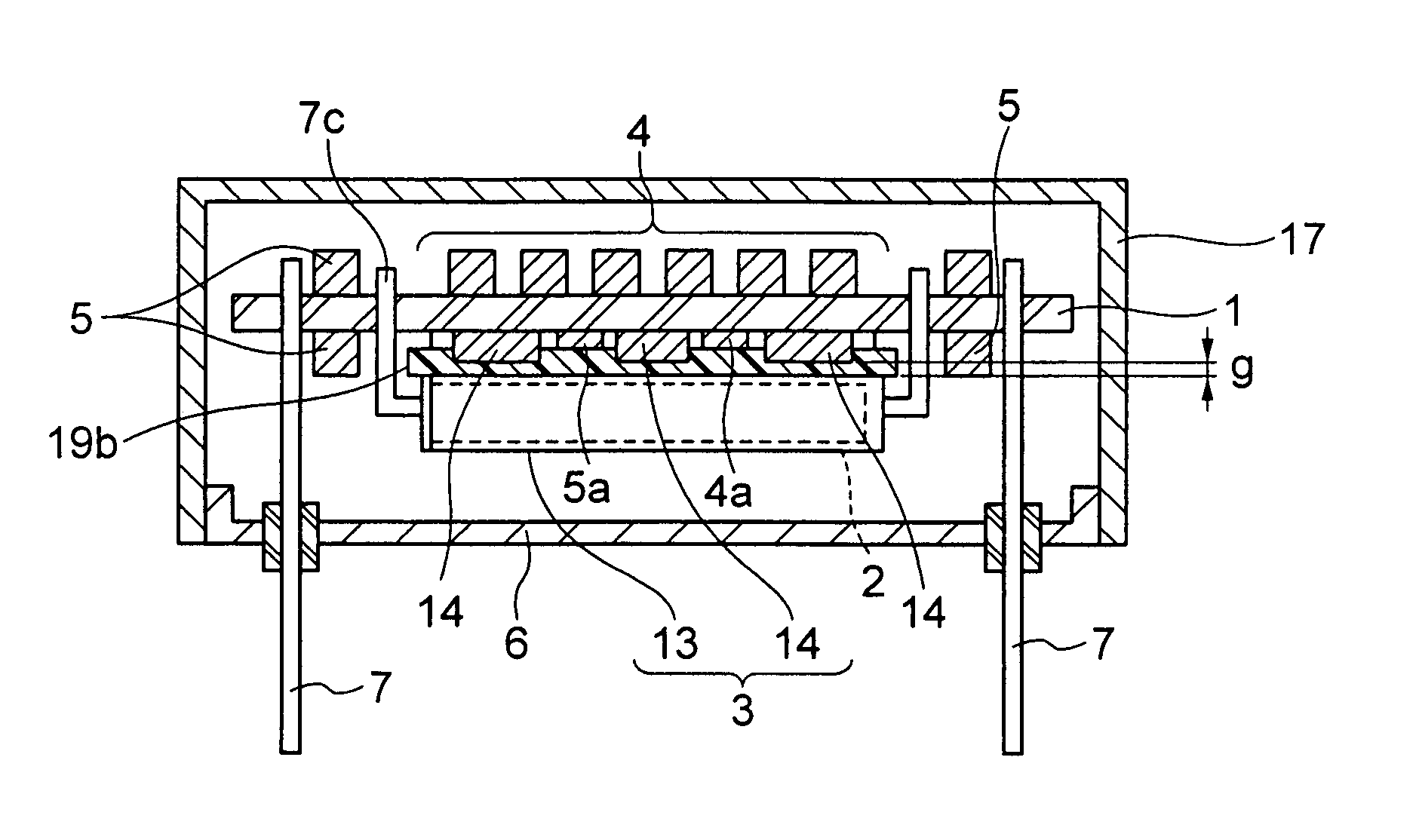
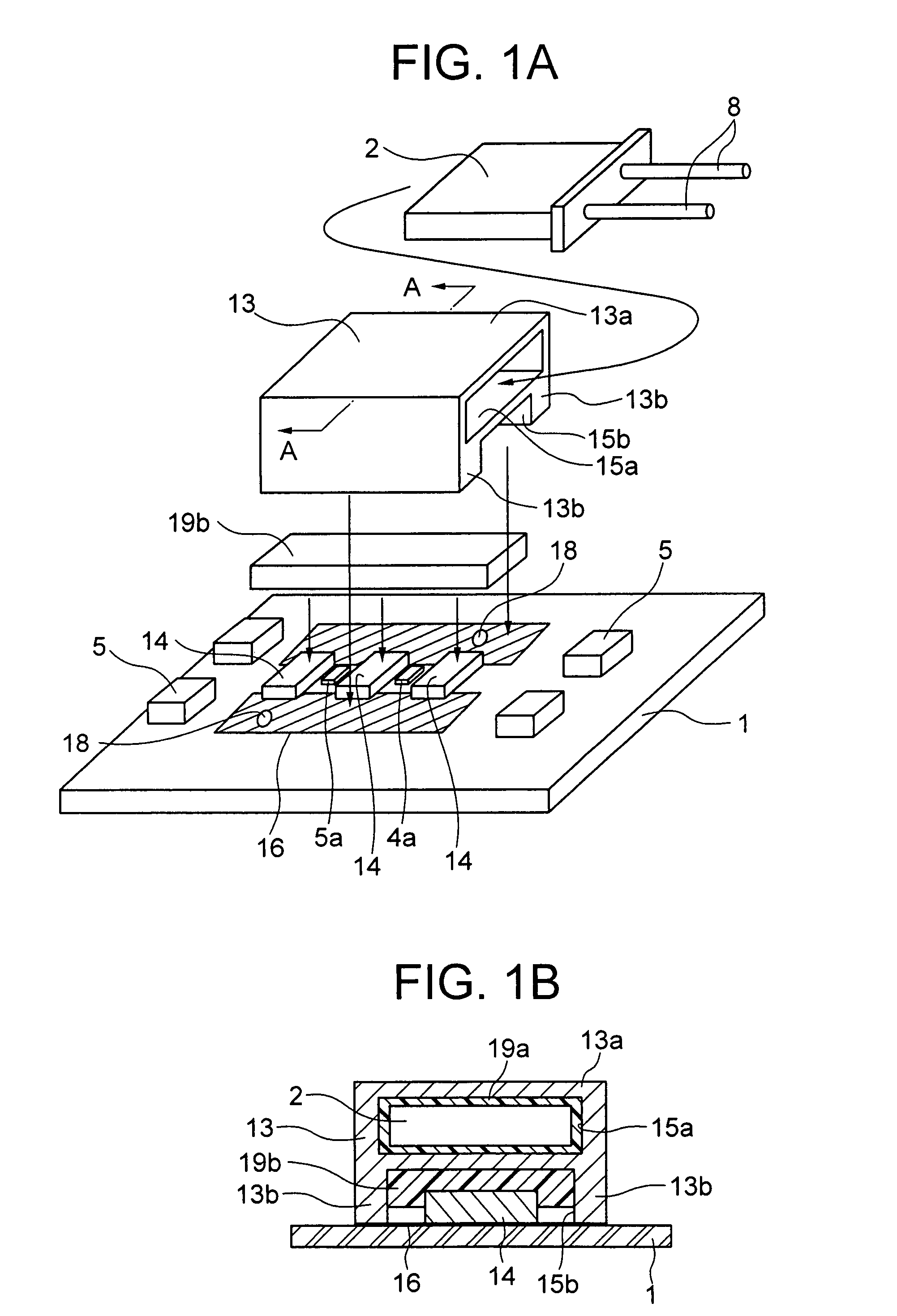
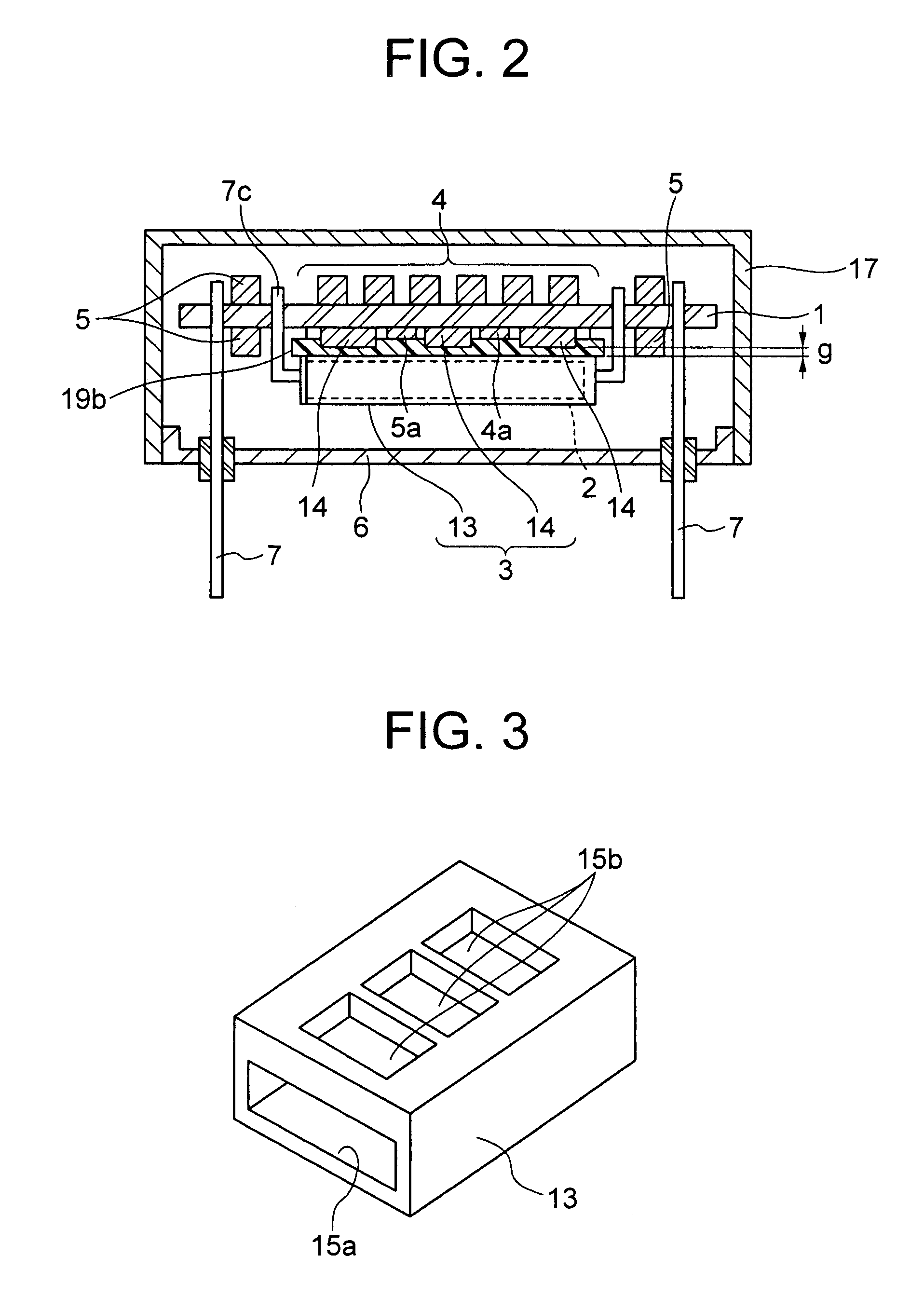
[0032]FIG. 1 and FIG. 2 are diagrams for explaining a highly stable oscillator of a first embodiment of the present invention, FIG. 1A being an assembly exploded view of the main points, and FIG. 1B being a sectional view of the main points in the width direction. FIG. 2 is a sectional view in the longitudinal direction showing a thermostat mainframe, with one leg omitted.

[0033]As shown in FIG. 1 and FIG. 2, the highly stable oscillator of the first embodiment of the present invention comprises; a crystal resonator 2 with lead wires 8 led out therefrom, a thermostat 3, oscillating elements 4 and temperature control elements 5, and a circuit board 1, with all arranged thereon. Here, the thermostat 3 comprises a thermostat mainframe (metallic cylinder) 13 and heat generating chip resistors 14. The thermostat mainframe 13 supported by a leg 7c with the circuit board 1 has a housing section 15a for the crystal resonator 2, and a cavity 15b as a space on one principal plane having legs 1...

second embodiment

[0041]FIG. 4 is a vertical sectional view of the main points of a highly stable oscillator, for explaining a second embodiment of the highly stable crystal oscillator of the present invention.

[0042]In the second embodiment of the present invention, the thermostat mainframe 13 comprises a pair of legs 13b extending from the opposite ends of a slab part 13a and forming a space section S in a cross sectional C shape. For example, the thermostat mainframe 13 is formed by folding a metal plate in the C shape.

[0043]Moreover, a crystal resonator 2 is arranged in the upper part (slab part 13a side) of a space section S and the crystal resonator 2 is adhered and heat bonded to the slab part 13a for example by a resin 19a being a thermo-conductive flexible material. On a circuit board 1 located at the lower part of the space section S, heat generating chip resistors 14 and a thermistor 5a and a voltage variable capacitative element 4a being highly heat sensitive elements are arranged. A resin...

third embodiment

[0046]FIG. 6 is a vertical sectional view of the main points of a third embodiment of a highly stable crystal oscillator of the present invention.

[0047]In the third embodiment, a thermostat mainframe 13 is constructed as a resonator container of a crystal resonator 2. On a lower face of the resonator container (crystal resonator 2), a heat generating chip resistor 16, a thermistor 5a and a voltage variable capacitative element 4a serving as highly heat sensitive elements, are arranged. Here, over the chip resistor 14 and the highly heat sensitive element (thermistor 5a) mounted on the circuit board 1, is coated a resin 19c composed of a thermo-conductive flexible material, and the crystal resonator 2 is superposed thereon, and the resin then cured.

[0048]According to such construction, the heat from the chip resistors 14 is transmitted to the crystal resonator 2 by the resin 19c serving as the thermo-conductive flexible material, so that the thermostat is formed. Therefore, a similar...


PUM


Abstract

To provide a highly stable crystal oscillator having increased thermal efficiency. The highly stable crystal oscillator comprises; a thermostat mainframe which maintains the temperature of a crystal resonator including a resonator container for sealing a crystal piece constant, an oscillating element which constitutes an oscillation circuit together with said crystal resonator, a temperature control element which controls the temperature inside of said thermostat mainframe, and a circuit board mounted with said thermostat mainframe, said oscillating element, and said temperature control element. The construction is such that a heat generating chip resistor and a highly heat sensitive element having a higher temperature dependency, among said oscillating element and said temperature control element, are arranged on one principal plane of said circuit board, and said heat generating chip resistor, said highly heat sensitive element, and said thermostat mainframe are directly heat bonded by a thermo-conductive material.

Description

BACKGROUND OF THE INVENTION[0001]1. Field of the Invention[0002]The present invention relates to an oven controlled crystal oscillator for high stability, using a thermostat (hereunder, “highly stable oscillator”), and particularly relates to a highly stable oscillator which is effective in heat utilization.[0003]2. Description of the Related Art[0004]In this kind of crystal oscillator, the operating temperature of the crystal resonator is maintained constant by an oven controlled using a thermostat so as to increase the frequency stability. For example, it has been used for base stations for optical communication. Recently, miniaturization has spread even to industrial crystal oscillators, requiring corresponding miniaturization.[0005]FIG. 7 is diagrams for explaining an example of a conventional crystal oscillator, FIG. 7A being a fragmentary vertical sectional view of a highly stable oscillator, and FIG. 7B being a conceptual diagram showing a procedure for inserting a crystal re...

Claims


Application Information

Patent Timeline
Patent Type & Authority Patents(United States)
IPC IPC(8): H03B5/32G05D23/19H03B5/04H03B5/36H05K1/02H05K1/18H05K3/30
CPCG05D23/19H03B5/04H03B5/36H05K1/0201H05K1/181H05K2201/10606H05K2201/10022H05K2201/10068H05K2201/10151H05K2201/10515H05K3/301
Inventor KATO, HIROSHIITO, MANABUUCHIDA, TAKESHI
Owner NIHON DEMPA KOGYO CO LTD
Why Eureka
Try Eureka