Malware scanning using a network bridge

a network bridge and malware technology, applied in the field of data processing systems, can solve the problems of increasing the cost of implementation, and increasing the complexity of networked computer systems, so as to achieve the effect of simplifying the load on the bridge and facilitating the operation of the network

Inactive Publication Date: 2006-04-04
MCAFEE LLC
View PDF20 Cites 60 Cited by
  • Summary
  • Abstract
  • Description
  • Claims
  • Application Information

AI Technical Summary

Benefits of technology

[0017]Whilst it would be possible for the bridge to buffer and re-transmit the data packets substantially unaltered once they had passed malware scanning, preferred embodiments are such that the malware scanner serves to forward a data file after scanning, and possible alteration via repair, to its intended recipient. This simplifies the load on the bridge and allows greater flexibility since the bridge does not try to reproduce exactly the same data packets.

Problems solved by technology

Networked computer systems are becoming increasingly common and complex.
A large organisation will typically have a considerable investment in terms of time and effort in its network topology design and configuration.
Once the topology of such a network has been established, changes in the topology, such as segment division and address changes, are time consuming and expensive to implement.
As computer systems and computer networks become increasingly important to their users, the threat posed by malware, such as computer viruses, Trojans, worms, banned computer programs or abusive e-mails, becomes increasingly significant.
Whilst the malware scanner 12 may provide effective malware defence, it brings with it a disadvantageous need to reconfigure the network which it is protecting.
Often specialist knowledge is required to make such reconfiguration changes and in a more sophisticated and complex network environment the difficulties can be considerable.
Thus, such alternative arrangements also carry with them similar significant disadvantages as those discussed in relation to FIG. 2.

Method used


Image

  • Malware scanning using a network bridge
  • Malware scanning using a network bridge
  • Malware scanning using a network bridge

Examples


Embodiment Construction

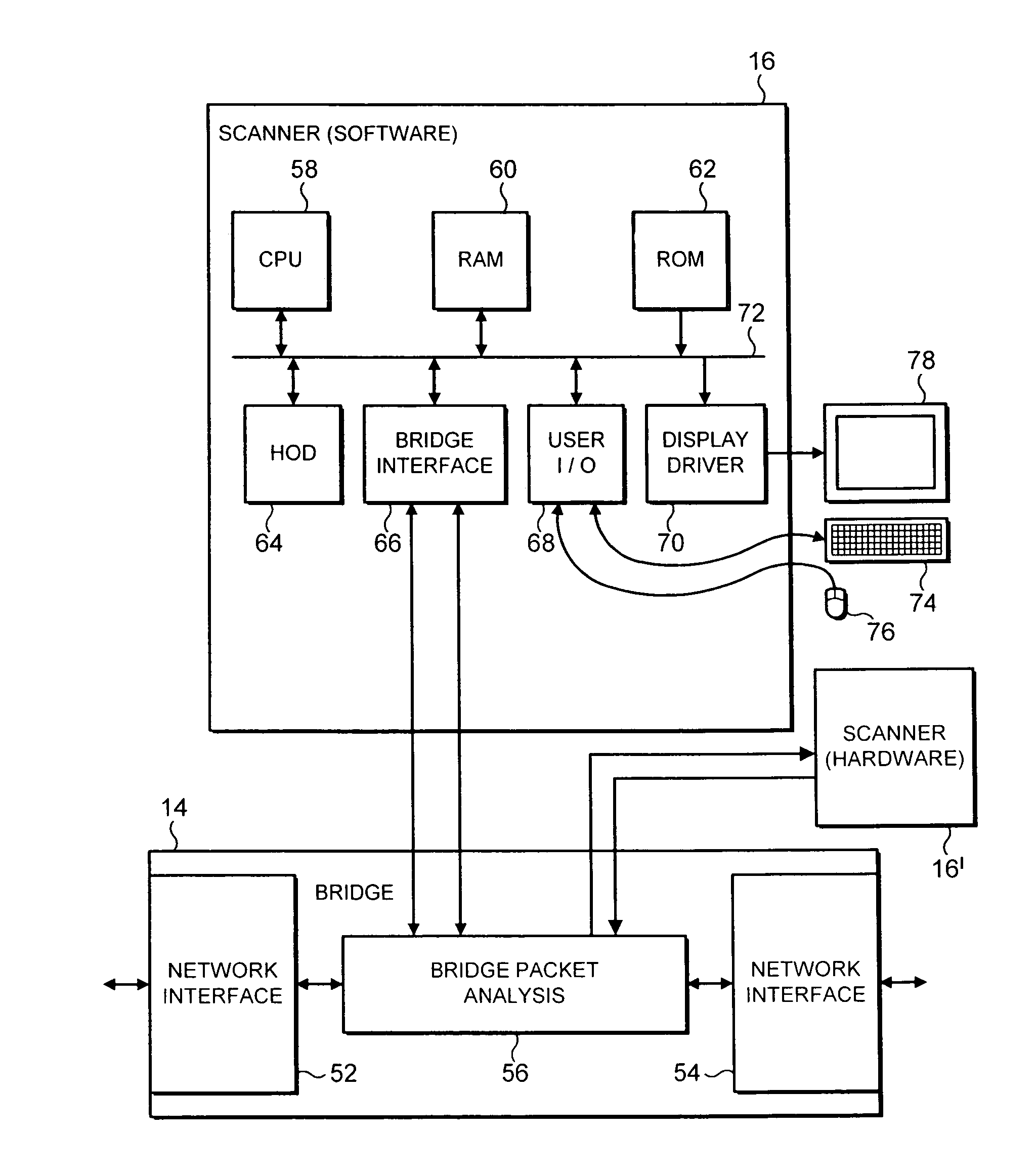
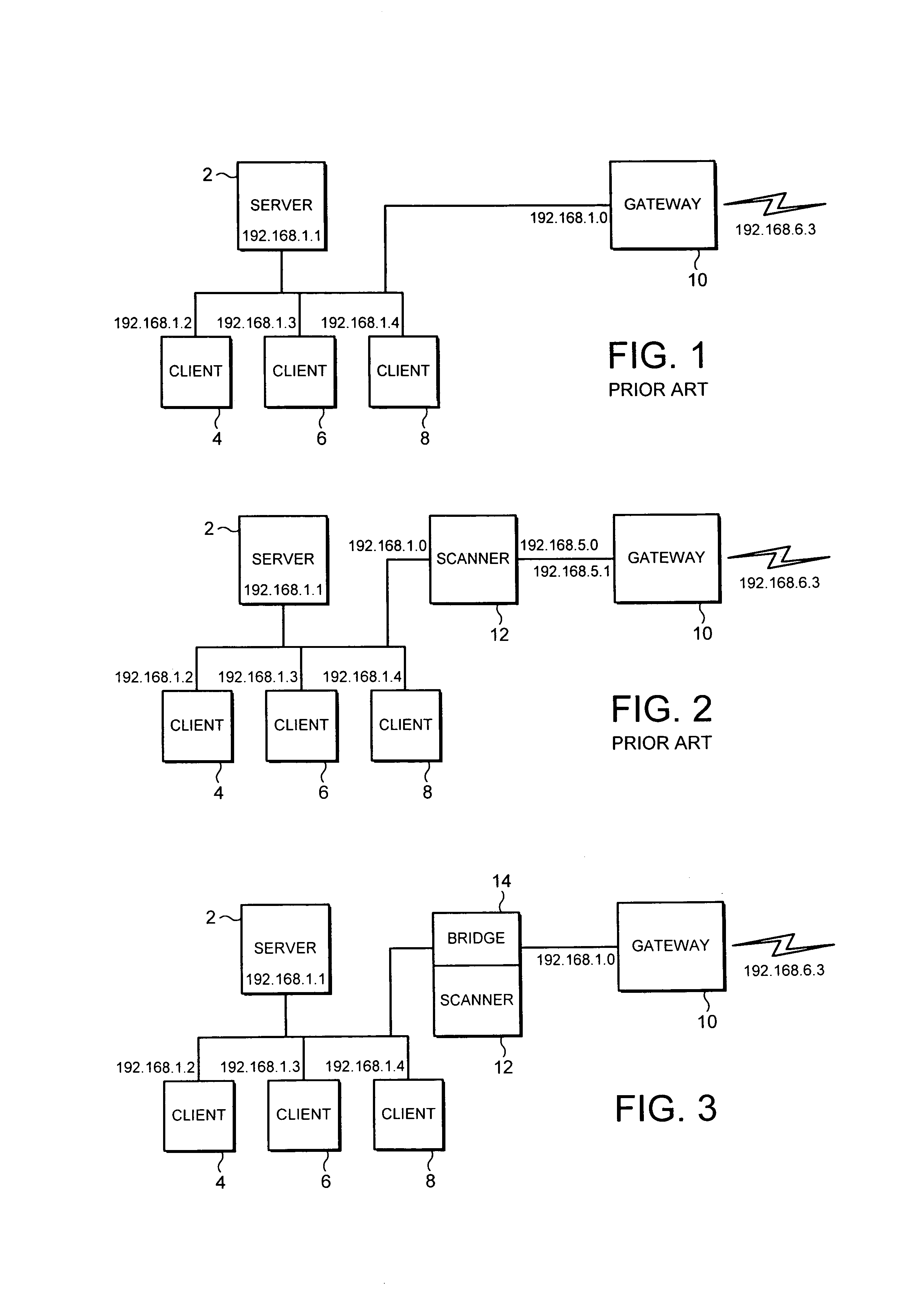
[0027]FIG. 3 schematically illustrates the network of FIG. 1 but in this case incorporating a network bridge 14 between the gateway computer 10 and the rest of the network segment. As such as a network bridge is effectively transparent to the data packets passing through it, at least in terms of their addressing, no configuration changes are required in the network segment illustrated in FIG. 3 upon introduction of the network bridge 14. A malware scanner 16 is associated with (e.g. incorporated within or coupled to) the network bridge 14 and serves to concatenate data files to scan at least some of the data packets passing through the network bridge 14. The arrangement illustrated in FIG. 3 would be appropriate to provide a malware scanner for SMTP data file types received by the gateway 10 and being sent to a mail server. Such SMTP data files are typically non-time critical and so a delay that might be introduced by the redirection of these data packets by the bridge 14 to the mal...


PUM


Abstract

A network bridge (14) has an associated malware scanner (16) that serves to concatenate portions of a data file from within data packets intercepted by the network bridge (14) and then scan the data file concerned before the data file is forwarded to its intended recipient by the network bridge (14). The network bridge (14) may be inserted in a network topology without requiring significant network configuration changes. The network bridge (14) may include a packet analysis unit (56) that serves to intercept only data packets having a predetermined network layer protocol or a predetermined application layer protocol.

Description

BACKGROUND OF THE INVENTION[0001]1. Field of the Invention[0002]This invention relates to the field of data processing systems. More particularly, this invention relates to the field of malware scanning, such as computer virus scanning or e-mail content scanning, as applied in network environments.[0003]2. Description of the Prior Art[0004]Networked computer systems are becoming increasingly common and complex. A large organisation will typically have a considerable investment in terms of time and effort in its network topology design and configuration. A large network may typically contain one or more gateways, routers and bridges operating in conjunction with one or more network segments. Once the topology of such a network has been established, changes in the topology, such as segment division and address changes, are time consuming and expensive to implement.[0005]As computer systems and computer networks become increasingly important to their users, the threat posed by malware,...

Claims


Application Information

Patent Timeline
Patent Type & Authority Patents(United States)
IPC IPC(8): H04L9/32G06F11/30H04L12/66H04L29/06
CPCH04L63/0209H04L63/145H04L63/0245
Inventor MAKINSON, GRAHAM ARTHURBAULK, EAMONN JOHNWOLFF, DANIEL JOSEPH
Owner MCAFEE LLC
Why Eureka
Try Eureka