Mechanical damper for air pad instability

a damper and air pad technology, applied in the field of mechanical dampers for air pad instability, can solve the problems of limited functional speeds friction and wear uneven rotation of the bearing pads, so as to reduce the noise of the fluid bearing system, reduce the wear of the component parts, and increase the rotational potential of the rotating gantry

Inactive Publication Date: 2006-04-04
KONINKLIJKE PHILIPS ELECTRONICS NV
View PDF11 Cites 26 Cited by
  • Summary
  • Abstract
  • Description
  • Claims
  • Application Information

AI Technical Summary

Benefits of technology

[0010]One advantage of the present invention resides in reduced wear of component parts of a fluid bearing.
[0011]Another advantage resides in reduced noise of a fluid bearing system.
[0012]Another advantage resides in increased rotational potential of the rotating gantry.
[0013]Another advantage resides in a damper that does not require attachment to a fixed body.
[0014]Numerous additional advantages and benefits of the present invention will become apparent to those of ordinary skill in the art upon reading the following detailed description of the preferred embodiment.

Problems solved by technology

Because there is physical contact between the bearings and the rotating gantry, there is friction and wear that occurs over usage of the scanner.
Additionally, functional speeds of the rotating gantry are limited by mechanical the bearings.
Because of the shape of the bearing pad, and the stress exerted on the bearing due to the weight of the gantry, minor pressure inconsistencies of the bearing can result in rotational wobbling of the bearing pads.
Air hammering can lead to premature wear of the bearing pads around the edges, where they frequently come into contact with the race, premature wear of the race for the same reason, and excess noise from the scanner.
This is a cumbersome setup, requiring amounts of space that might not be available in a cramped gantry system.

Method used


Image

  • Mechanical damper for air pad instability
  • Mechanical damper for air pad instability
  • Mechanical damper for air pad instability

Examples


Embodiment Construction

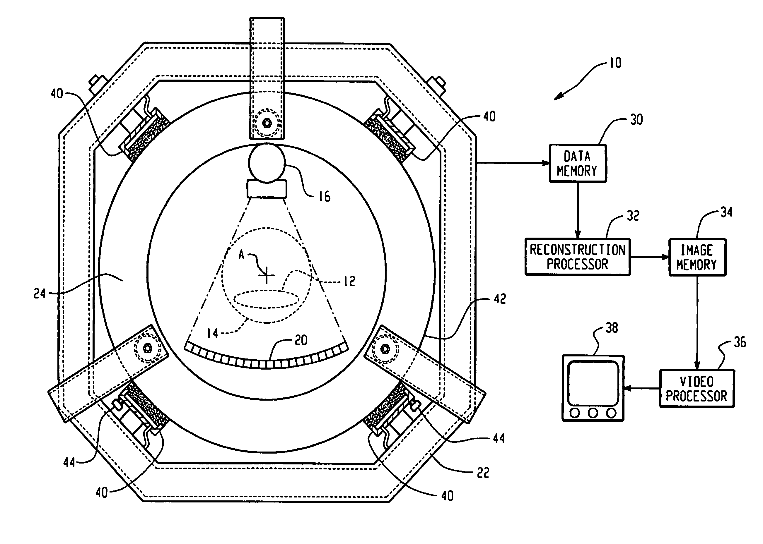
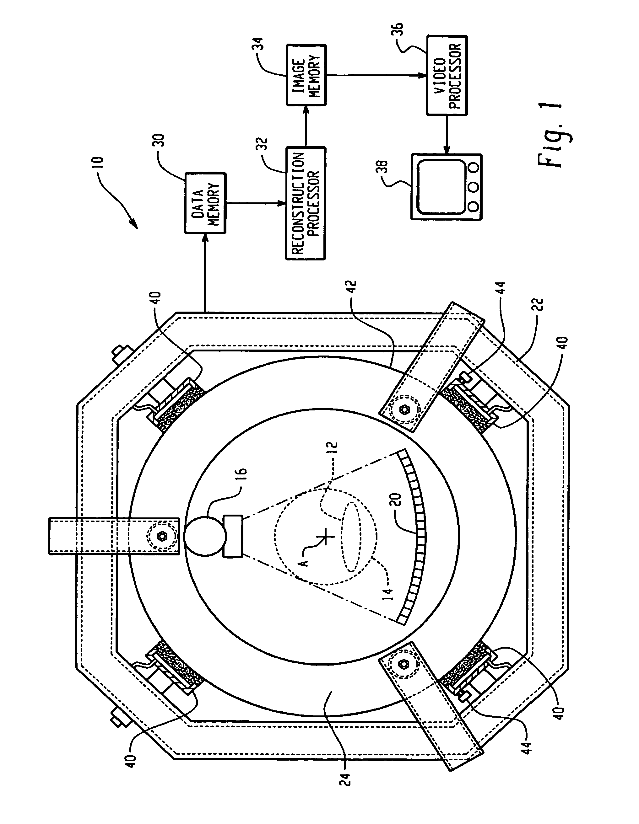
[0020]With reference to FIG. 1, a CT scanner 10 includes a subject couch 12 for moving a subject disposed thereon into and out of an imaging region 14. X-rays from an x-ray source 16 are shaped and collimated into a fan beam, pass through the imaging region 14 and are detected by a detector assembly 20 on the far side of the imaging region 14. In the illustrated 3rd generation embodiment, the source 16 rotates concurrently with the detector assembly 20, always remaining 180° around the imaging region 14 from the detector assembly 20 as it rotates around an axis A. Alternately, a stationary ring of individual detectors on a stationary gantry 22 can replace the detector array 20, as in a 4th generation CT scanner.

[0021]Intensities of detected x-rays are collected in a data memory 30 as a rotating gantry 24 rotates the x-ray source 16 about the subject. As the data is collected, a reconstruction processor 32 applies a convolution and backprojection algorithm, or other suitable reconstr...


PUM


Abstract

In a diagnostic imaging apparatus, a stationary gantry (24) and a rotating gantry (22) are interfaced by a plurality of air bearing elements (40). Lower air bearing elements bear the weight of the rotating gantry (22) which induce air hammering phenomena at a characteristic vibration frequency. To counteract the air hammering, a damping assembly (44) is mounted to at least one lower bearing element (40). The damping assembly (44) includes a damping mass (46) and an elastomeric connector (48) that are tuned to a frequency near the air hammer frequency to absorb the vibrational energy and damp the air hammer vibrations.

Description

BACKGROUND OF THE INVENTION[0001]The present invention relates to medical imaging arts. In particular, it relates to a rotating gantry such as those found in 3rd and 4th generation CT scanners, and will be described with particular reference thereto. However, the invention will also find application in conjunction with other systems, such as nuclear cameras that use rotating gantries, and is not limited to the aforementioned application.[0002]Typically, 3rd and 4th generation CT scanners are equipped with mechanical ball or roller bearing systems. Because there is physical contact between the bearings and the rotating gantry, there is friction and wear that occurs over usage of the scanner. Additionally, functional speeds of the rotating gantry are limited by mechanical the bearings.[0003]In an effort to overcome the limitations of mechanical bearing systems for such medical imagers, fluid bearing systems are being used. Some fluid bearing systems include porous bearing pads that fi...

Claims


Application Information

Patent Timeline
Patent Type & Authority Patents(United States)
IPC IPC(8): A61B6/03F16C32/06
CPCA61B6/035F16C32/067F16C32/0666F16C32/0618F16C2300/14F16C2316/10
Inventor BRUNNETT, WILLIAM C.
Owner KONINKLIJKE PHILIPS ELECTRONICS NV
Why Eureka
Try Eureka