Compression support sleeve

Inactive Publication Date: 2006-04-11
L&R USA INC
36 Cites 78 Cited by

AI-Extracted Technical Summary

Problems solved by technology

The upright posture of the human body renders it particularly susceptible to strains, sprains and other injuries which are generally manifested by swelling, inflammation and discomfort.
When severe, an injury may result in impaired mobility and necessitate restriction of movement and activity.
The body is also subject to formation of fibrin clots which may obstruct vessels in the peripheral circulation when the body is in the prone position for prolonged periods.
In addition to localized morbidity, such clots may also break free and travel to the heart or lungs causing more serious damage.
Orthopedic injuries have economic as well as physical repercussions for professional athletes engaged in competitive sports.
Sidelined athletes lose not only the opportunity to perform, but experience a reduction in their overall level of fitness during periods of restricted activity, necessitating a period of retraining prior to resumption of competition.
However, non professional athletes also experience discomfort when injured and their level of physical fitness is also impaired by injury-enforced inactivity.
Moreover, amateur athletes may be more likely to be susceptible to injury, since they generally lack the advice of professional trainers as well as the fitness and judgment developed by professional athletes.
Those who engage in infrequent bouts of strenuous exercise without training are most at risk of injury.
However, even the well-trained amateur athlete is subject to occasional strains and sprains.
Some individuals are particularly at risk of injury because of previous traumatic injury which has left continuing weakness in a joint or limb.
However, the skin-contacting layer is quite slick, and the support tends to migrate along the skin unless it is sized and custom fitted to the limb of a wearer.
Known knitted, woven and laminate materials tend to experience slippage along the limb and to wrinkle or bunch up, causing compression of the limb to be uneven.
Such shifting and uneven displacement of the material against ...

Method used

[0026]The outer elastomeric polymer layer 14 presents a smooth surface 21, which facilitates free movement of clothing over the sleeve 1, while providing resistance to abrasion and wear. Various constructions of sleeves having layers similar to layers 11, 12, 13, 14 and 15 have been previously offered by others for such devices as wet suits and medical devices. Such a sleeve of five layers is depicted in U.S. Pat. No. 5,735,807 of Cropper for use as a knee compression support, which is incorporated herein by reference.
[0028]The microdots 23 are spaced and preferably of generally circular configuration, having a thickness of from about 1 to 4 mils preferably about 2 mils, and with a diameter of from about 10 to 50 mils in diameter with about 25 mils in diameter being preferred. Also, preferably the dots are spaced a distance from each other approximately equal to the radius of the dots. The microdots 23 are imprinted upon the fabric by application of a preselected pressure which causes them to extend outwardly from the fabric surface 22 preferably about 2 mils. The miorodots 23 are applied over substantially all of the inner surface 22 of the polymer layer 15. Because of the elastomeric nature of silicone patterns when stretched, the silicone microdots 23 impart additional compression to the garment 1 and spacing facilitates breathing of the fabric. In certain embodiments, the size and distribution of the microdots 23 are varied in order to provide additional compression at predetermined locations. Such variable compression enables the garment to provide differential support and is particularly desirable in certain applications such as, for example, ankle braces.
[0030]While normally not necessary with the microdots 23, the sleeve 1 may also include one or more ribs or stays 24, which are formed of a flexible synthetic resinous material to impart additional rigidity and support to the garment or assist in application of the sleeve 1 to the knee joint 2. The stays 24 are secured in place on either side and at the ends by seams 25, which may be sewn or fusion welded. One or more loops 26 extend upwardly from s...

Benefits of technology

[0017]The principal objects and advantages of the present invention are: to provide a compression support which stays in place on the body of a wearer while maintaining breathability of the underlying skin; to provide such a support which is of multilayer laminate construction; to provide such a support which is light weight and comfortable to a wearer; to provide such a support which does not irritate the skin of a wearer; to provide such a support which has enhanced compression properties; to provide such a support which eliminates the requirement of rigid or semi-rigid shape maintaining structure such as stays, straps or sewn in elastic or impermeable compositions to prevent garment migration; to provide a material for such a support which has a skin-contacting surface having a high coefficient of friction as well as allowing breathability; to provide such a material which reduces garment migration; to provide such a which reduces the likelihood of skin irritation caused by shifting of the material against the skin; to provide such a material which imparts additional compression to ...

Abstract

A multilayer compression support sleeve construction. The laminate material includes a thin polyurethane film coated on both surfaces with an adhesive. A stretchable elastomeric polymer material is bonded to each of the adhesive surfaces. A substantial portion of one of the elastomeric polymer surfaces is coated with a discontinuous layer of silicone microdots. The microdots are applied by gravure roll printing to project a uniform distance above the elastomeric polymer surface to form small tacky dots. The laminate material is fabricated into a sleeve with the material oriented so that the microdot coated face is adjacent the skin of the wearer. Microdots may be applied in a predetermined pattern in order to impart enhanced compression to certain areas of the support sleeve. The resulting support sleeve retains its breathability while presenting a nonslip inner surface which prevents migration of the garment on the skin of the wearer during exercise. The garment does not cause irritation to the underlying skin.

Application Domain

Technology Topic

Image

  • Compression support sleeve
  • Compression support sleeve
  • Compression support sleeve

Examples

  • Experimental program(1)

Example

[0024]As required, detailed embodiments of the present invention are disclosed herein; however, it is to be understood that the disclosed embodiments are merely exemplary of the invention, which may be embodied in various forms. Therefore, specific structural and functional details disclosed herein are not to be interpreted as limiting, but merely as a basis for the claims and as a representative basis for teaching one skilled in the art to variously employ the present invention in virtually any appropriately detailed structure.
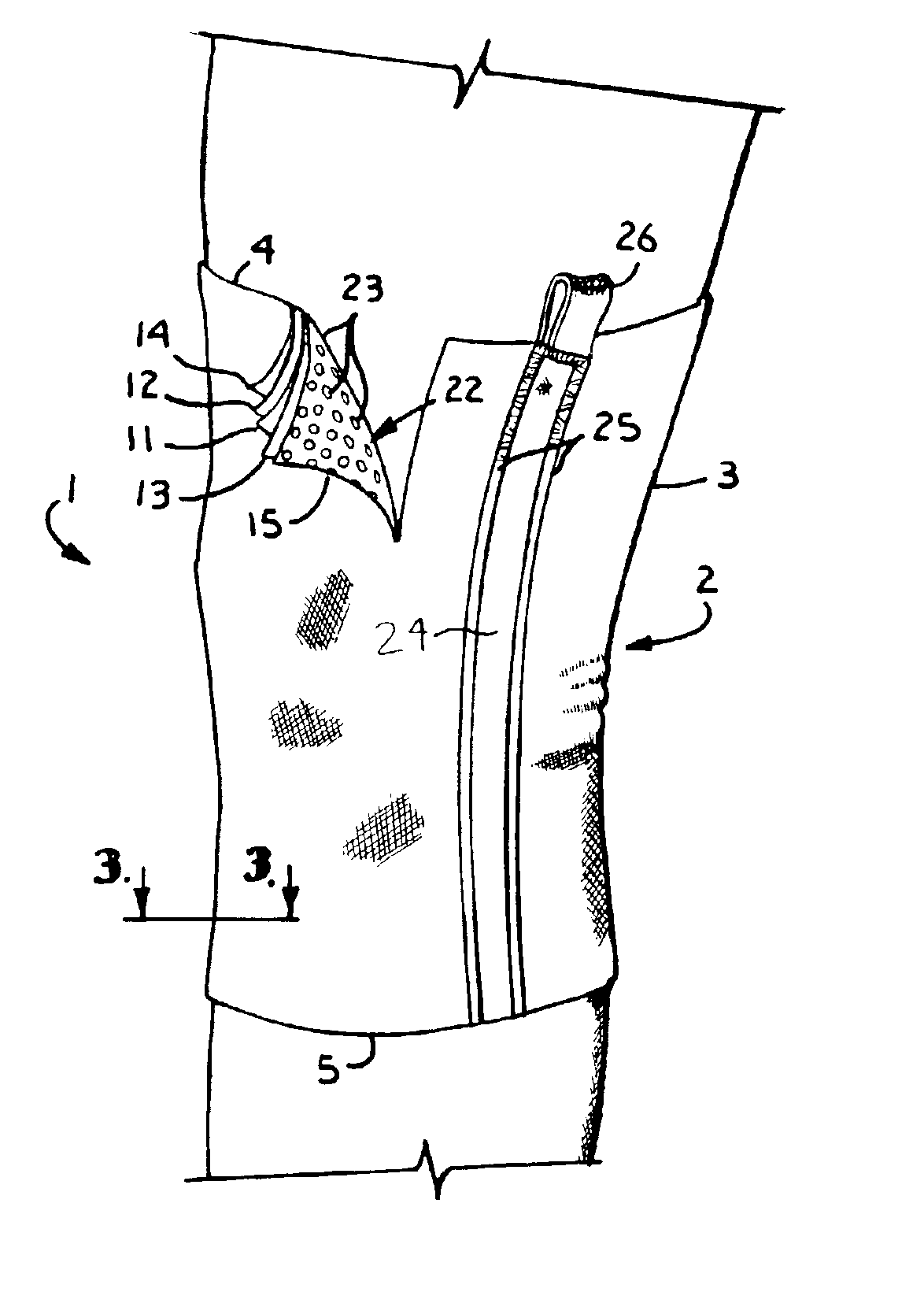
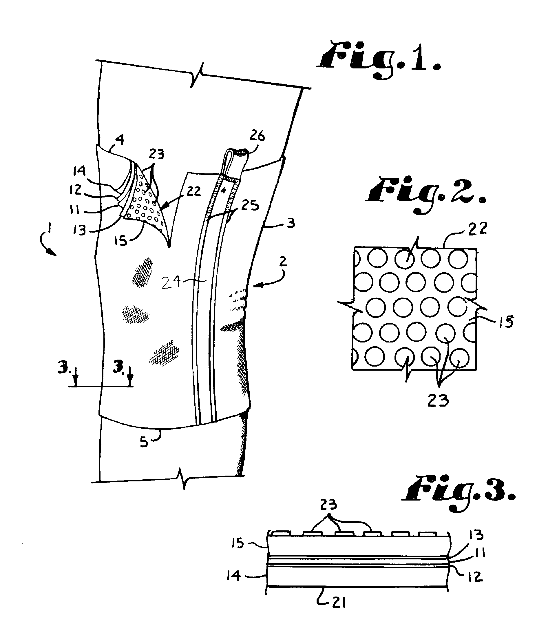
[0025]The reference numeral 1 generally identifies a compression support sleeve in accordance with the present invention and the sleeve 1 is depicted in place over human leg knee joint area 2. The sleeve 1 includes a generally tube-shaped member 3 of multilayer construction, having an upper end 4 and a lower end 5. As best shown in FIGS. 1 and 3, a central film 11 is sandwiched between outer and inner adhesive layers 12 and 13. A flexible and resilient film composition is required for the film 11 in order to permit stretching of the sleeve 1, as it is put on and to accommodate movement of the underlying joint or limb during use. Polyurethane having a thickness of about 2 mil is preferred, although another suitable polymeric film may be employed and thickness may vary in accordance with desired characteristics of the sleeve 1. The adhesive or heat and pressure sensitive glue layers are bonded respectively to outer and inner layers of elastomeric polymer material 14 and 15. Any suitable adhesive which is compatible with both the polyurethane film layer 11 and the elastomeric polymer layers 14 and 15 may be employed. The polymer layers 14 and 15 are preferably constructed of a spandex fiber such as is sold under the trademark Lycra by DuPont Chemical Co., however, other materials function satisfactorily for the purpose.
[0026]The outer elastomeric polymer layer 14 presents a smooth surface 21, which facilitates free movement of clothing over the sleeve 1, while providing resistance to abrasion and wear. Various constructions of sleeves having layers similar to layers 11, 12, 13, 14 and 15 have been previously offered by others for such devices as wet suits and medical devices. Such a sleeve of five layers is depicted in U.S. Pat. No. 5,735,807 of Cropper for use as a knee compression support, which is incorporated herein by reference.
[0027]An inner, slip resistant surface 22 is formed by a layer of discontinuous microdots of a tacky substance 23, which covers a substantial portion of the surface 21. Silicone has been found to be particularly suitable for this purpose because it is extremely compatible with human skin, and may be compounded into an adhesive fluid for application which retains a slightly tacky surface when dry.
[0028]The microdots 23 are spaced and preferably of generally circular configuration, having a thickness of from about 1 to 4 mils preferably about 2 mils, and with a diameter of from about 10 to 50 mils in diameter with about 25 mils in diameter being preferred. Also, preferably the dots are spaced a distance from each other approximately equal to the radius of the dots. The microdots 23 are imprinted upon the fabric by application of a preselected pressure which causes them to extend outwardly from the fabric surface 22 preferably about 2 mils. The miorodots 23 are applied over substantially all of the inner surface 22 of the polymer layer 15. Because of the elastomeric nature of silicone patterns when stretched, the silicone microdots 23 impart additional compression to the garment 1 and spacing facilitates breathing of the fabric. In certain embodiments, the size and distribution of the microdots 23 are varied in order to provide additional compression at predetermined locations. Such variable compression enables the garment to provide differential support and is particularly desirable in certain applications such as, for example, ankle braces.
[0029]While the microdots can be constructed of any material compatible with the skin a silicon rubber is preferable, especially a silicon rubber that is the reaction product of 5 to 10% VI/ST dimethyl-methylvinylsiloxane, 60 to 80% vinylpolydimethylsiloxane, 10 to 30% D4 and HMDZ treated silicon dioxide reacted with 60 to 80% vinylpolydimethylsiloxane, 5 to 10% VI/ST dimethylvinylsiloxane, 1 to 5% polymethylhydrogensiloxane and 10 to 30% D4 and HMDZ treated silicon dioxide. Such a composition is available from Enterprise Coatings Co. Ltd.
[0030]While normally not necessary with the microdots 23, the sleeve 1 may also include one or more ribs or stays 24, which are formed of a flexible synthetic resinous material to impart additional rigidity and support to the garment or assist in application of the sleeve 1 to the knee joint 2. The stays 24 are secured in place on either side and at the ends by seams 25, which may be sewn or fusion welded. One or more loops 26 extend upwardly from sleeve upper end 4 to facilitate pulling the garment on and positioning it snugly in place over a selected limb or joint.
[0031]While a generally tubular sleeve 1 has been depicted and described, those skilled in the art will appreciate that such compression support garments may be fabricated to include gussets or seams or in the form of stockings, spiral constructions for use on the ankles and elbows as well as planar bandages which may be wound around a limb or joint in overlapping fashion and held in place by hook and loop fasteners or clips.
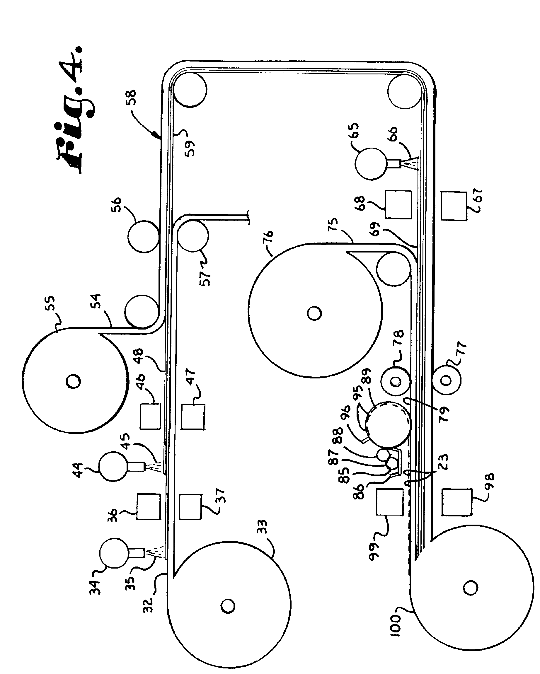
[0032]A method of manufacture of the material of sleeve 1 is depicted schematically in FIG. 4 which includes providing a substrate 32 having suitable release properties to permit casting and easy removal of a polyurethane solution. The substrate 32 is preferably supplied on a spool 33. As the substrate 32 is unrolled into an assembly line, it passes a spray station 34, which applies a polyurethane fluid 35 to one surface of the substrate 32. The polyurethane coated substrate 32 passes through a series of drying ovens 36 and 37, which dry the polyurethane 35 into a 2 mil film 59 on the substrate 32.
[0033]The film-coated substrate passes a spray station 44, which applies an adhesive solution 45 onto the surface. Preferably, the station 44 sprays adhesive solution 45 onto the film-coated substrate in an even, continuous layer. In other alternate embodiments, the spray station 44 may be operated intermittently or the distance between the spray heads may be set to deliver a discontinuous layer of adhesive solution 45. Once coated with adhesive solution 45, the polyurethane film-coated substrate 32 passes through a second series of ovens 46 and 47, where the solvent is evaporated from the adhesive solution to form an adhesive layer 48.
[0034]Elastomeric fabric 54, such as a spandex fiber of about 20 mils, is supplied, preferably on a spool 55. Knitted nylon tricot fabric, especially as sold under the trademark LYCRA by E. I. DuPont de Nemours, is preferred because it provides a superior laminate construction which is long wearing and extremely comfortable to the wearer, although any other suitable knitted, woven or nonwoven fabric such as cotton, rayon, other stretchable synthetic fiber or blend thereof may be employed. The fabric 54 is unwound onto the surface of the adhesive layer 48 and is pressed into the adhesive 48 at elevated temperature by a series of rollers 56 and 57 to form a fabric/adhesive/film laminate 58. The laminate 58 is then stripped from the substrate 32, exposing an uncoated polyurethane film surface 59.
[0035]The laminate 58 passes a spray station 65 which again sprays an adhesive solution 66 onto the uncoated polyurethane film surface 59. Once coated with adhesive solution 66, the laminate 58 passes through a third series of drying ovens 67 and 68, where the solvent is evaporated from the adhesive solution to form an adhesive layer 69.
[0036]Additional elastomeric tricot fabric 75 of about 20 mils in thickness is supplied on a spool 76. The fabric 75 is unwound onto the surface of the adhesive layer 69 and is pressed into the adhesive 69 by rollers 77 and 78 to form a fabric/adhesive/polyurethane/adhesive/fabric laminate material 79.
[0037]The silicone microdots 23 are applied to one of the fabric surfaces of the laminate 79 by a process such as gravure printing. In the preferred rotogravure method, a suitably compounded silicone fluid 85 is supplied in a trough 86 for imprinting onto one surface of the laminate. Silicone is preferred because of the compatibility of its cured silicone gel with the skin and because the cured gel retains a slightly tacky surface having a high coefficient of friction against the skin.
[0038]A first rotating cylinder 87 rests in the trough 86, and by rotary movement thereof, its surface receives a coating of the silicone 85. A second rotating cylinder 88, is positioned in contact with cylinder 87 and elevated slightly above the trough 86 so as to receive a coating of the silicone solution 85 from the first cylinder 87 during rotation, and to permit any excess solution to drain back into the trough 86. A rotating gravure cylinder 89 is positioned so as to make contact with cylinder 88 as well as the surface of laminate 79 during its rotation.
[0039]The surface of cylinder 89 is etched or engraved to form a preselected pattern of spaced, generally circular recesses 95, each having a predetermined diameter and depth. As gravure cylinder 89 rotates against cylinder 88, the recesses 95 are filled with silicone 85. A doctor blade 96 removes the excess silicone 85 from the surface of the gravure cylinder 89, but not from the recesses. Continued rotation of the gravure cylinder 89 brings the silicone filled recesses 95 into contact with the surface of laminate 79, where the silicone 85 is imprinted as raised silicone microdots 23.
[0040]Gravure cylinder 89 exerts a preselected pressure against the laminate 79 during the printing process in order to achieve a selected depth of imprint of the microdots 23 into the laminate 79. In this manner, the depth of the recesses 95 and imprinting pressure cooperatively determine the depth of the imprinted microdots 23 on the surface of the imprinted laminate 97 The size, depth, distribution and arrangement of the recesses 95 on the gravure cylinder 89 may be preselected to imprint microdots 23 in any desirable pattern which serves to reduce garment migration, provide additional areas of compression, or even to provide brand identification.
[0041]The imprinted laminate 97 passes through a series of circulating air ovens 98, 99 for evaporation of any solvent residue and curing of the silicone solution to a tacky gel. The laminate 97 is then wound onto rolls 100 of manageable size. The silicone imprinted laminate 97 may also be joined under heat and pressure with a release-coated protective backing prior to winding on rolls 100. The backing may be removed after complete cure of the silicone, to expose a multilayer laminate material having a permanently tacky imprinted surface with spacing between the dots to facilitate breathing of the material.
[0042]The material thus produced may be formed into completed sleeves 1, stockings and other types of compression support having sewn or fused darts, gussets, and seams. The supports may also include fasteners such as for example, hooks, zippers, buttons and the like.
[0043]It is to be understood that while certain forms of the present invention have been illustrated and described herein, it is not to be limited to the specific forms or arrangement of parts described and shown.

PUM

PropertyMeasurementUnit
Pressure
Elastomeric
Electrical resistance
tensileMPa
Particle sizePa
strength10

Description & Claims & Application Information

We can also present the details of the Description, Claims and Application information to help users get a comprehensive understanding of the technical details of the patent, such as background art, summary of invention, brief description of drawings, description of embodiments, and other original content. On the other hand, users can also determine the specific scope of protection of the technology through the list of claims; as well as understand the changes in the life cycle of the technology with the presentation of the patent timeline. Login to view more.

Similar technology patents

Stem cell microparticles and miRNA

ActiveUS10406182B2Reduce migrationInhibit migrationPharmaceutical delivery mechanismNervous system cellsStem cell lineNeural stem cell
Owner:RENEURON LTD

Hair dye composition

PendingCN112770721AReduce migrationImprove hair colorCosmetic preparationsHair cosmeticsAromatic alcoholHair dyes
Owner:HOYU CO LTD

Egg handling system

ActiveUS20100059337A1Increase stiffnessReduce migrationPackaging eggsConveyor partsTransfer systemTransfer mechanism
Owner:FPS FOOD PROCESSING SYST BV

Classification and recommendation of technical efficacy words

  • Reduce migration
  • Light weight

Expandable fixation mechanism

ActiveUS20060095078A1Reduce migrationMigrationSpinal electrodesImplantable neurostimulatorsBiomedical engineeringInsertion device
Owner:MEDTRONIC INC

Covered stents with degradable barbs

InactiveUS20080249598A1Reduce migrationStentsBlood vesselsProsthesisExtrusion
Owner:BOSTON SCI SCIMED INC

Anti-migration Micropatterned Stent Coating

ActiveUS20150051693A1Maintaining luminal patencyReduce migrationStentsSynthetic resin layered productsProsthesisPolymer
Owner:BOSTON SCI SCIMED INC

Protected dry composites

InactiveUS20050186305A1Reduce shrinkageReduce migrationAnimal feeding stuffAccessory food factorsBiologyAmino acid
Owner:RGT UNIV OF CALIFORNIA

Protection of anodes for electrochemical cells

InactiveUS20100104948A1Light weightAlkaline accumulatorsElectrode manufacturing processesSulfur containingElectrochemical cell
Owner:SION POWER CORP

Housing for an Implantable Medical Device

ActiveUS20090171420A1Light weightIncrease manufacturing efficiencyInternal electrodesExternal electrodesMagnetic fluxElectrical and Electronics engineering
Owner:CYBERONICS INC
Why Eureka
Try Eureka