
Nozzle/mixer assembly

a technology of nozzles and mixers, which is applied in the direction of lighting and heating apparatus, furniture, transportation and packaging, etc., can solve the problems of affecting the operation temperature of the reactor, affecting the efficiency of the reactor, so as to reduce the operating temperature and reduce the limitation of mass transfer, the effect of high liquid product yield

Inactive Publication Date: 2006-04-11
AEC OIL SANDS
View PDF16 Cites 34 Cited by
  • Summary
  • Abstract
  • Description
  • Claims
  • Application Information

AI Technical Summary

Benefits of technology

"The invention is a nozzle / mixer assembly that is used to mix and contact solid particles with liquid droplets in a fluidized column. The assembly includes an atomizing nozzle that injects a jet of atomized liquid droplets into the column, where it mixes with the particles and gas. A mixer is used to temporarily confine the jet and stream of particles, allowing them to mix and contact. This results in improved liquid yield, reduced fouling, and reduced reactor operating temperature. The technical effects of this invention include improved mixing and contact between solid particles and liquid droplets, leading to improved process efficiency and product yield."

Problems solved by technology

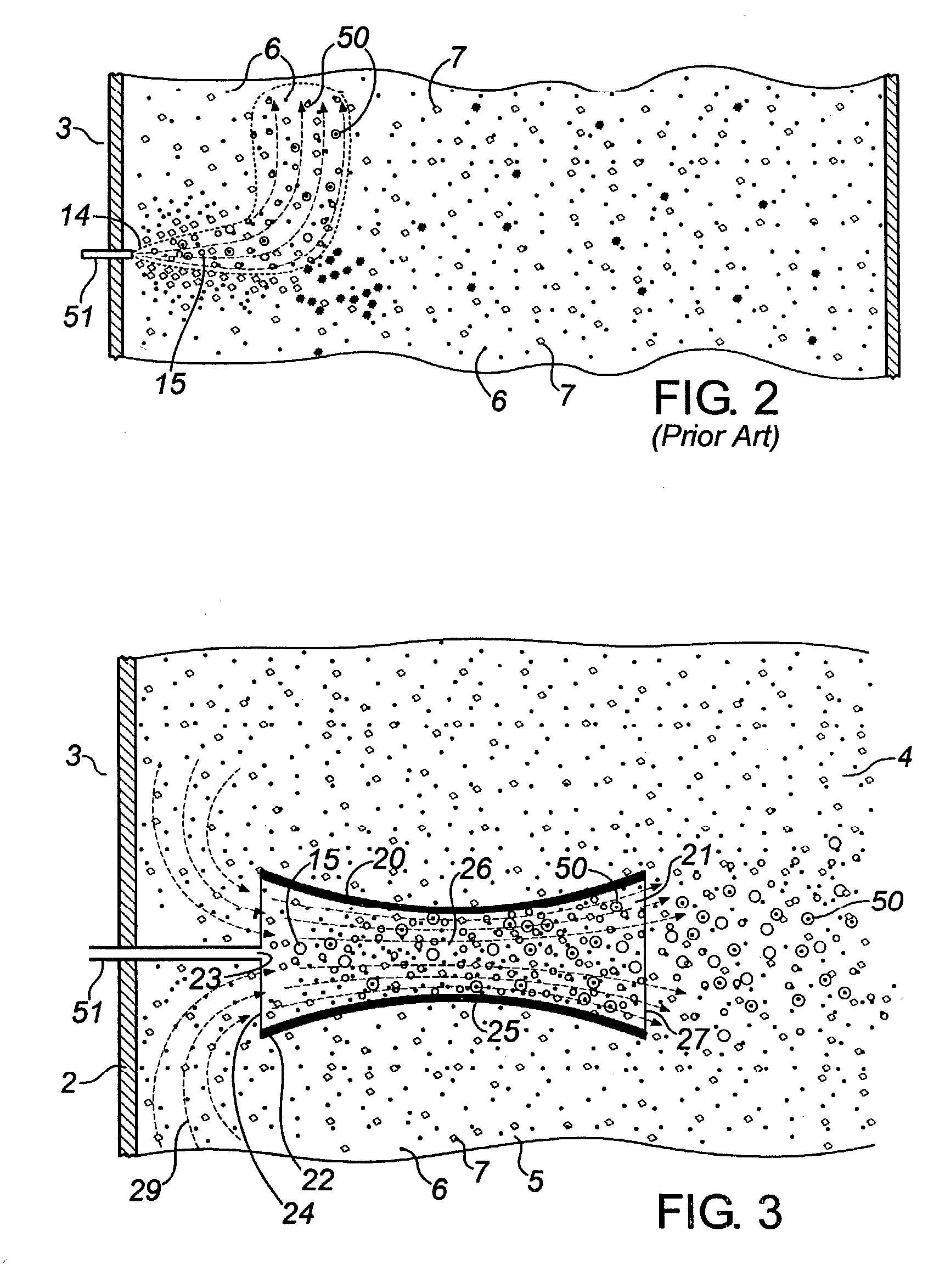
However, it was noted that agglomerates of oil-wet particles were being formed.
They would drop within the reactor chamber and foul the reactor internals at the base of the chamber.
This had been a long standing problem associated with fluid coking operations.
It became apparent that the high velocity jet of minute oil droplets, supplied by the aforesaid pre-mixer and nozzle assembly, did not eliminate the problem.
These facts suggested to us that some hot coke particles were being coated with too thick a coating of oil, creating a mass transfer limitation.
The oil coatings on the hot coke particles convert to volatized liquid product, gas-make and coke over time, primarily in the secondary dispersion zone;that oil-wet agglomerates appear at the end of the plume and then tend to drop to the bottom of the reactor;that the mixing of oil droplets with hot coke particles in the secondary dispersion zone is relatively ineffective.

Method used


Image

  • Nozzle/mixer assembly
  • Nozzle/mixer assembly
  • Nozzle/mixer assembly

Examples


Embodiment Construction

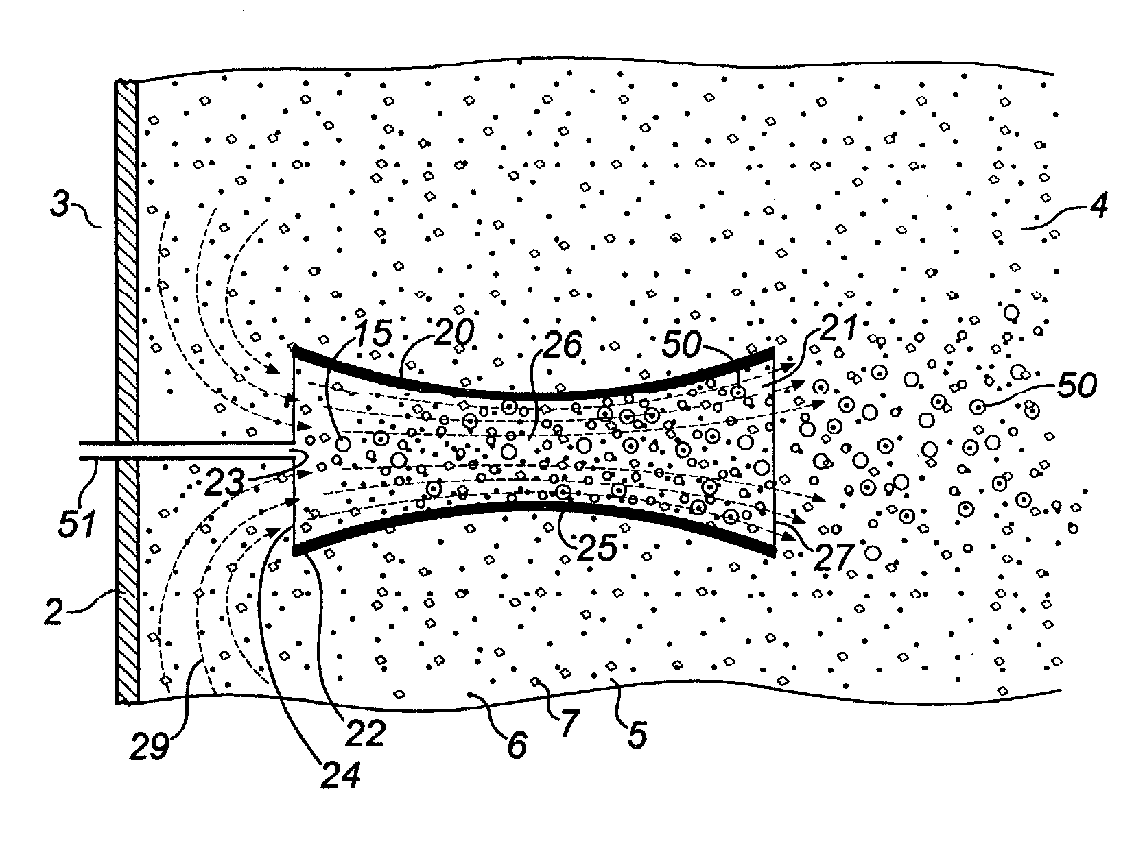
[0038]Having reference to FIG. 8, a nozzle / mixer assembly 1 is mounted to the tubular side wall 2 of a fluid coking reactor 3. The reactor 3 has an interior chamber 4 containing a fluidized column or bed 5 of hot coke particles 6 suspended in fluidizing steam bubbles 7.

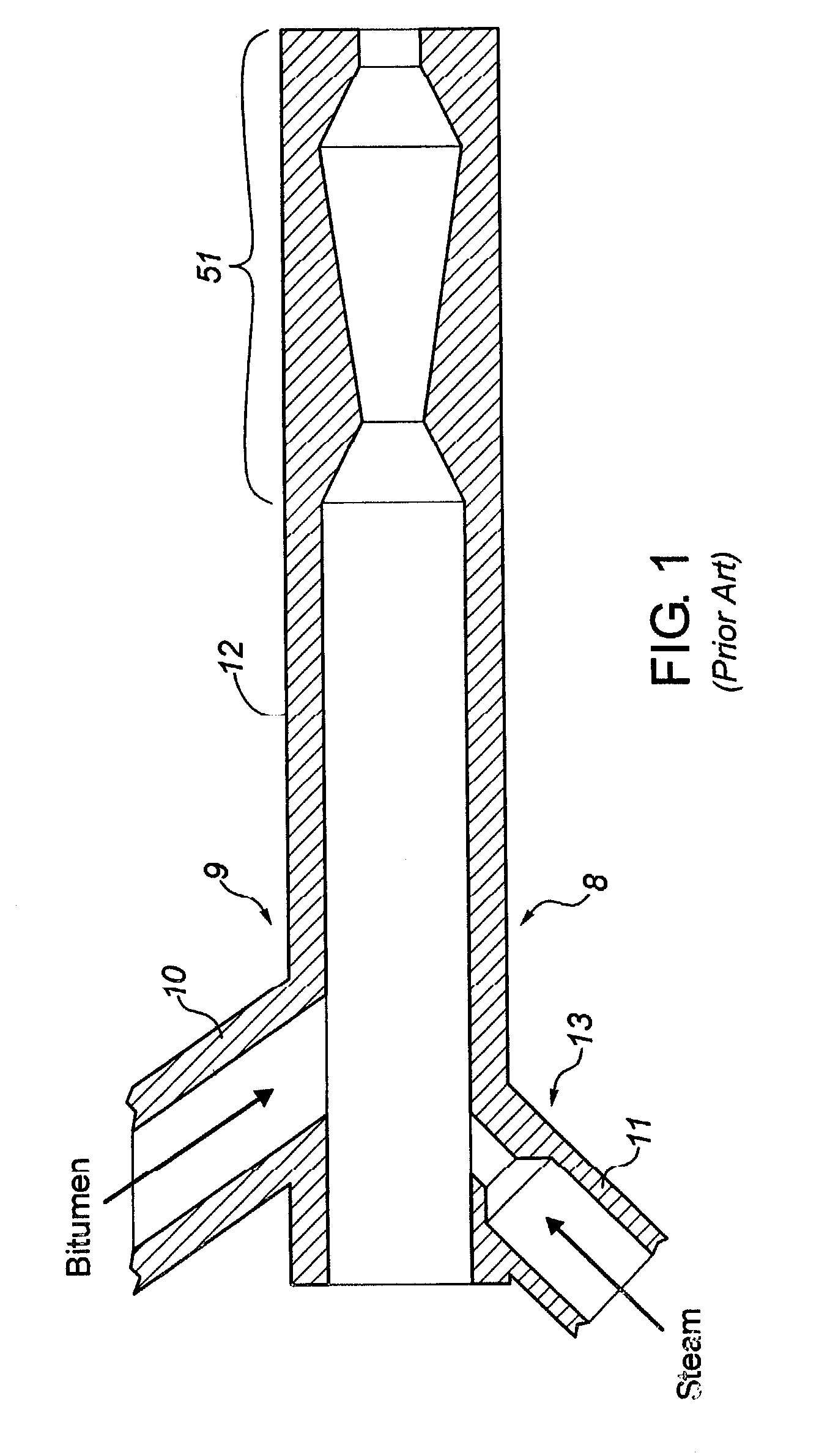
[0039]Having reference to FIGS. 1, 2 and 8, the nozzle / mixer assembly 1 comprises a pre-mixer and an atomizing nozzle assembly 8 extending through the reactor side wall 2 into the chamber 4. The atomizing nozzle 51 may be such as shown in U.S. Pat. No. 6,003,789. The atomizing nozzle 51 is the end piece on a pre-mixer 9. The pre-mixer 9 comprises intersecting pipes 10, 11 supplying bitumen and steam, respectively, under pressure to a nozzle feed pipe 12. An orifice mixing nozzle 13 is mounted in the pipe 11. The bitumen / steam mixture is discharged through the constrictive atomizing nozzle 51 in the form of a high velocity jet 14 of atomized bitumen droplets 15 dispersed in carrier gas 16 (i.e. the steam).

[0040]Having ...


PUM

PropertyMeasurementUnit
sizeaaaaaaaaaa
lengthaaaaaaaaaa
lengthaaaaaaaaaa

Abstract

A bitumen / steam pre-mixer and atomizing nozzle combine to produce a jet of minute liquid droplets (bitumen) in carrier gas (steam). The jet is injected into a draft tube mixer positioned in a fluid bed of hot coke particles suspended in steam and contained within a fluid coking reactor. The movement of the jet through the draft tube passageway induces a stream of coke particles in steam to be drawn into the passageway, where the jet and stream mix vigorously and bitumen droplets have an enhanced probability of contacting coke particles.

Description

FIELD OF THE INVENTION[0001]The invention relates to a method and nozzle / mixer assembly for mixing a jet of atomized liquid droplets suspended in carrier gas with an entrained stream of fluidizing gas carrying solid particles, so that the droplets have opportunity to contact the particles.[0002]The assembly and method are particularly useful for mixing a stream of hot coke particles and fluidizing gas, drawn from a fluidized bed in a fluid coking reactor, with a jet of atomized oil droplets and carrier gas being injected into the fluidized bed.BACKGROUND OF THE INVENTION[0003]The invention was developed in connection with a research program dedicated to increasing the proportion of hot coke particles, present in a fluid coking reactor, which are contacted by atomized oil or bitumen droplets injected into the fluid bed. The invention will be described in that particular context. However it is contemplated that the invention will be useful in other applications (such as fluid catalyst...

Claims


Application Information

Patent Timeline
Patent Type & Authority Patents(United States)
IPC IPC(8): C10G9/32B01J8/18B01F5/02B01J8/24B01J19/26
CPCB01F5/0212B01J19/26B01J8/1827B01F25/211
Inventor CHAN, EDWARD W.MCDOUGALL, STEVENKNAPPER, BRIAN
Owner AEC OIL SANDS
Learn More