Deep red phosphor for general illumination applications

a phosphor and general illumination technology, applied in the manufacture of electrode systems, electric discharge tubes/lamps, discharge tubes luminescent screens, etc., can solve the problems of failure of led-phosphor systems, and inability to meet lighting needs

Inactive Publication Date: 2006-04-11
GENERAL ELECTRIC CO
View PDF38 Cites 140 Cited by
  • Summary
  • Abstract
  • Description
  • Claims
  • Application Information

AI Technical Summary

Problems solved by technology

Until quite recently, LEDs have not been suitable for lighting uses where a bright white light is needed, due to the inherent color of the light produced by the LED.
Such a device, while suitable for limited applications, fails in applications where a true bright white light of high intensity and brightness is desired.
In addition to this somewhat limited emission intensity, the color output of such an LED-phosphor system varies greatly due to frequent, unavoidable routine deviations from desired parameters (i.e. manufacturing systemic errors) during the production of the light.
Unfortunately, the thickness of the phosphor layer is difficult to control during large-scale production of LED-phosphor lamp systems, and the variations in phosphor thickness often result in relatively poor lamp to lamp color control.

Method used


Image

  • Deep red phosphor for general illumination applications
  • Deep red phosphor for general illumination applications
  • Deep red phosphor for general illumination applications

Examples


fourth embodiment

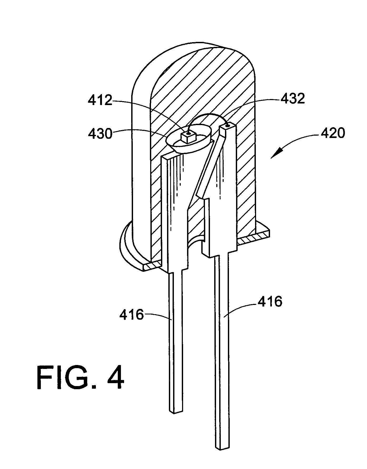
[0032]As shown in a fourth embodiment in FIG. 4, the LED chip 412 may be mounted in a reflective cup 430. The cup 430 may be made from or coated with a reflective material, such as alumina, titania, or other dielectric powder known in the art. A preferred reflective material is Al2O3. The remainder of the structure of the embodiment of FIG. 4 is the same as that of any of the previous Figures, and includes two leads 416, a conducting wire 432 electrically connecting the LED chip 412 with the second lead, and an encapsulant material 420.

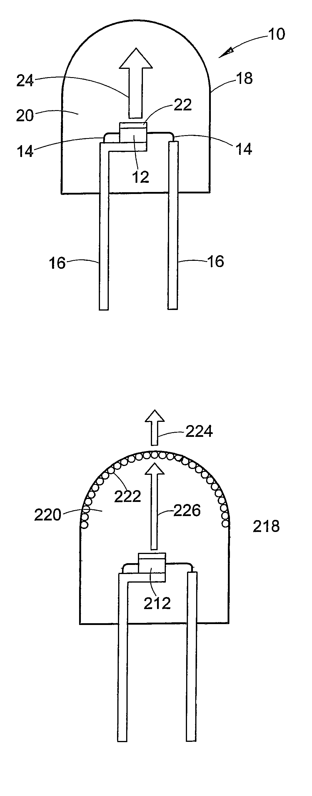
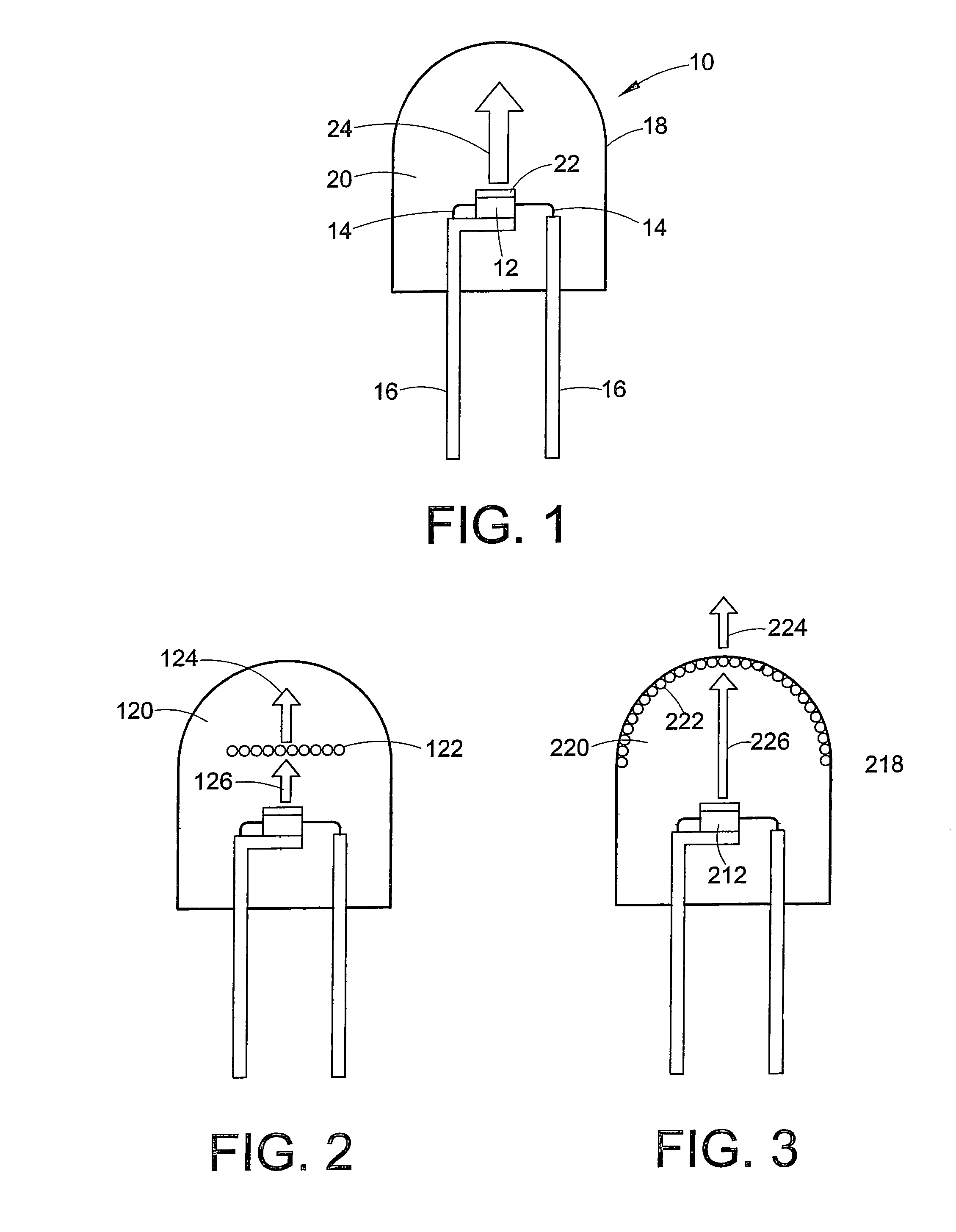
[0033]In one embodiment, the phosphor composition 22 used in the invention is a composition having the general formula (Ba,Sr,Ca)3MgSi2O8:Eu2+, Mn2+. The total doping levels of Eu2+ and Mn2+ can range from 0.1 to about 40%, with Eu2+ ranging from about 0.1–40% and Mn2+ ranging from 0.1 to 20%. In such an embodiment, the resulting lighting system will produce a light having a deep red color, the characteristics of which will be discussed in more detail...

second embodiment

[0041]In a second embodiment, the phosphor composition includes a blend of the (Ba,Sr,Ca)3MgSi2O8:Eu2+, Mn2+ phosphor described above and a green, blue and, optionally a blue-green, yellow-orange, and / or red emitting phosphor to create a white light emitting phosphor blend. Any known green and blue phosphor suitable for use in UV LED systems may be used. In addition to the green and blue phosphors, a yellow-orange and / or red phosphor may be used in the blend to customize the white color of the resulting light. Other blue-green, green, orange or additional phosphor may also be included based on the needs of the manufacturer. While not intended to be limiting, suitable phosphorfor use in the blend with the (Ba,Sr,Ca)3MgxSi2O8:Eu2+, Mn2+ phosphor include:

Blue:

[0042](Ba,Sr,Ca)5(PO4)3(Cl,F,Br, OH):Eu2+, Mn2+, Sb3+[0043](Ba,Sr,Ca)MgAl10O17:Eu2+, Mn2+[0044](Ba,Sr,Ca)BPO5:Eu2+, Mn2+[0045](Sr,Ca)10(PO4)6*nB2O3:Eu2+[0046]2SrO*0.84P2O5*0.16B2O3:Eu2+[0047]Sr2Si3O8*2SrCl2:Eu2+[0048]Ba3MgSi2O8:Eu...


PUM

PropertyMeasurementUnit
wavelengthaaaaaaaaaa
peak emission wavelengthaaaaaaaaaa
wavelengthaaaaaaaaaa

Abstract

A light emitting device including a UV semiconductor light source and a phosphor blend including a blue emitting phosphor, a green emitting phosphor and a deep red emitting phosphor comprising (Ba,Sr,Ca)3MgxSi2O8:Eu2+, Mn2+, wherein 1≦x≦2. Also disclosed is a phosphor blend comprising a blue emitting phosphor, a phosphor, a green emitting phosphor and a red emitting phosphor comprising (Ba,Sr,Ca)3MgxSi2O8:Eu2, Mn2+.

Description

BACKGROUND OF THE INVENTION[0001]The present invention relates to phosphor compositions, particularly phosphors for use in lighting applications. More particularly, the present invention relates to a phosphor for converting UV light to red light for use in an LED or LCD and a lighting apparatus employing the same.[0002]Light emitting diodes (LEDs) are semiconductor light emitters often used as a replacement for other light sources, such as incandescent lamps. They are particularly useful as display lights, warning lights and indicating lights or in other applications where colored light is desired. The color of light produce by an LED is dependent on the type of semiconducting material used in its manufacture.[0003]Colored semiconductor light emitting devices, including light emitting diodes and lasers (both are generally referred to herein as LEDs), have been produced from Group III–V alloys such as gallium nitride (GaN). To form the LEDs, layers of the alloys are typically deposit...

Claims


Application Information

Patent Timeline
Patent Type & Authority Patents(United States)
IPC IPC(8): H01L33/00C09K11/08C09K11/77H01L33/50
CPCC09K11/7734H01L33/507H01L33/502H01L2924/181H01L2224/48247H01L2224/48257C09K11/77342H01L2924/00012
Inventor SETLUR, ANANT ACHYUTSRIVASTAVA, ALOK MANICOMANZO, HOLLY ANN
Owner GENERAL ELECTRIC CO
Why Eureka
Try Eureka