Display apparatus and image signal processing apparatus

a technology of image signal processing and display apparatus, which is applied in the field of display apparatus and image signal processing apparatus, can solve the problems of long way to win, high degree of technological difficulty for larger sizes, and inferiority of projection-type display apparatus in general use in terms of picture quality, and achieve the effect of high picture quality

Inactive Publication Date: 2006-04-11
CANON KK
View PDF14 Cites 38 Cited by
  • Summary
  • Abstract
  • Description
  • Claims
  • Application Information

AI Technical Summary

Benefits of technology

[0012]An objective to be solved by the present invention application is to realize high picture quality in a projection-type display apparatus or direct-view-type apparatus irradiating lights to a light modulating element to construct display image planes by its penetrating light or reflected light.
[0013]Another objective of the mode of embodiments of the present application is to provide a system to attain high picture quality of a high dynamic range to be attached to features of large image plane and high accuracy of the projection-type display apparatus.
[0014]Moreover, the above described system is to attain the above described objective with an existing device, which might be a liquid crystal device and DMD having levels thereof, in combination, and is a low-cost and practical system.
[0022]In this invention, a memory is provided so as to temporally store the display signal after calculation, and therefore, even if light quantity control takes time, it will become possible that the signal to be inputted to the light modulating element are easily brought into synchronization with the light quantity control corresponding with the signals.
[0043]Here, the above described light quantity controlling means preferably set so as to increase the above described light quantity from the above described first stage to the above described second stage when the value determined by the above described calculation changes in the first direction to exceed the first threshold value, and so as to decrease the above described light quantity from the above described second stage to a stage with less light quantity when the value determined by the above described calculation changes in the second direction being opposite against the above described first direction to exceed the second threshold value set in the side of the above described second direction than the above described first threshold value. In addition, here the stage of the above described low light quantity being the above described first stage can be controlled easily.

Problems solved by technology

However, these projection-type display apparatuses is inferior to CRT display tubes in general use in terms of picture quality, and for high picture quality display (display demanded for quality feeling), users tend to use CRT display tubes even when the image plane size is small.
However, in case of a CRT system, the size thereof is around 40 inches at largest due to limitation in a tube, etc., giving rise to a problem that there exists a high degree of technological difficulty for larger sizes.
Accordingly, they used to have a problem that there is a long way to win against the above described CRT system in terms of one point of high picture quality (high dynamic range).
In addition, a direct-view-type LCD likewise used to have a problem that its dynamic range is low, compared with the CRT.

Method used


Image

  • Display apparatus and image signal processing apparatus
  • Display apparatus and image signal processing apparatus
  • Display apparatus and image signal processing apparatus

Examples


embodiment 1

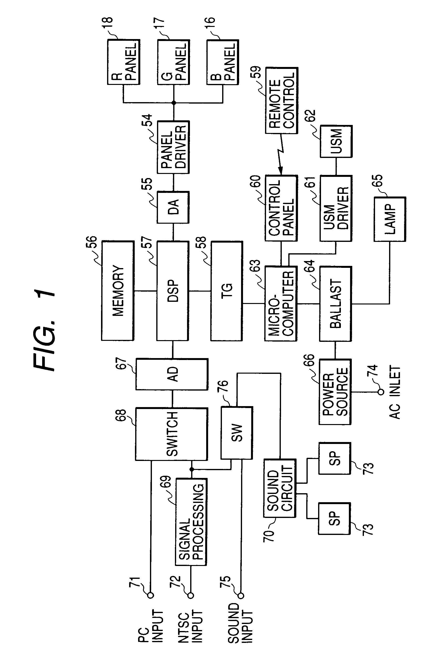
[0074]FIG. 1 shows a block diagram of a signal processing apparatus related to an embodiment of the present invention.

[0075]In FIG. 1, reference numerals 18, 17 and 16 denote liquid crystal panels in correspondence with R, G and B color display respectively, reference numeral 54 denotes a driver circuit to supply each liquid crystal panel with applying signals and power source, reference numeral 55 denotes a DA converter and reference numeral 56 denotes a memory. The memory 56 holds current display data as well as data to be displayed in the next frame and the like. Reference numeral 57 denotes a DSP unit to execute not only processing such as gamma adjustment, conversion of interlace signals to non-interlace signals, resolution conversion in the case where the pixel amount of liquid crystal panel currently in use does not corresponds with the pixel amount of the input signal and color adjustment, etc. but also operation to calculate signal levels of respective colors for irradiatio...

embodiment 2

[0090]In Embodiment 1, a construction using a liquid crystal panel as the light modulating element has been described, but in the present embodiment, as the light modulating element, a light modulating element, also known as a DMD, displaying images by integrating micromirrors and controlling reflecting directions of irradiation lights with respective mirrors is used. Description on portions in common with Embodiment 1 will be omitted.

[0091]FIG. 5 is a block diagram involving units of calculating quantity controlling light quantity and of signal gain setting related to a second embodiment of the present invention.

[0092]In FIG. 5, the image signals inputted from the signal input terminal 501 are amplified by an analog amplifying unit 502 constructing an adjusting circuit at an amplifying ratio calculated by a unit of calculating amplification ratio 507. Next, subject to conversion into digital signals with an A / D converter 503, a luminance detection unit 504 constructing input image ...

embodiment 3

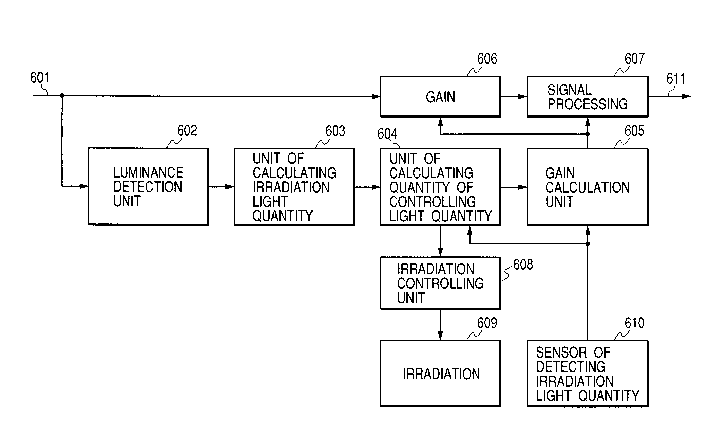
[0098]FIG. 6 is a block diagram of a light quantity controlling unit and a signal gain setting unit related to a third embodiment of the present invention. In the present embodiment, light quantity controlling is executed by feeding back light quantity being illuminated to a light modulating element to a calculating unit.

[0099]In FIG. 6, based on image signals inputted from an input end 601, a luminance detection unit 602 calculates luminance distribution and a unit of calculating irradiation light quantity 603 calculates irradiation light quantity. Next, a unit of calculating quantity of controlling light quantity 604 calculates quantity of controlling light quantity and an irradiation controlling apparatus 608 drives irradiation 609.

[0100]A sensor of detecting irradiation light quantity 610 detects luminance of irradiation light 609 to be given to the unit of calculating quantity of controlling light quantity 604 as well as to the gain calculation unit 605. The gain calculation un...


PUM

PropertyMeasurementUnit
sizesaaaaaaaaaa
rotary angleaaaaaaaaaa
thresholdaaaaaaaaaa

Abstract

To attain high image quality such as high resolution and high dynamic range in a display apparatus for irradiating light generated by a light source onto a light modulating element and for forming a display image plane from the light transmitted through or reflected by the light modulating element.The apparatus is configured to control irradiation light quantity, in which the high image quality is provided by an unit for temporarily storing display signal, an unit for adjusting signal under an analog state, a unit for differentiating a rate of change in light quantity at the time of increase and at the time of decrease and a unit for controlling light quantity to resemble hysteresis.

Description

BACKGROUND OF THE INVENTION[0001]1. Field of the Invention[0002]The present invention relates to a display apparatus as well as a signal processing apparatus for a display apparatus that is suitable for application to a large image plane / highly accurate display apparatus such as a liquid crystal display and a projector, etc.[0003]2. Related Background Art[0004]Advent of the multimedia age brings display apparatus to all the scenes, and since projection type display apparatus is efficient compared with other systems in particular, front projectors are in common use for presentations, etc. and rear projectors are in common use for domestic theaters.[0005]In recent years, CRT projection is being replaced by a projector in a liquid crystal panel system and a DMD (digital mirror device, for which reference should be made to Japanese Patent Application Laid-Open No. 10-78550) method modulating light quantity by changing angles of an mirror which are turning to spread because they are appr...

Claims


Application Information

Patent Timeline
Patent Type & Authority Patents(United States)
IPC IPC(8): G09G3/34G02F1/13G02F1/1335G03B21/00G03B21/14G09G3/36G09G5/10H04N5/74H04N9/31
CPCG09G3/3406H04N9/3197H04N9/3105H04N9/3155H04N9/3179G09G5/10G09G2320/0276G09G2320/0285G09G2320/0626G09G2320/0646G09G2320/0653G09G2320/066G09G2320/0673G09G2330/021G09G2360/145G09G2360/16G09G3/3611
Inventor SAKASHITA, YUKIHIKO
Owner CANON KK
Why Eureka
Try Eureka