Dermoscopy epiluminescence device employing multiple color illumination sources

a technology of epiluminescence device and dermoscopy, which is applied in the direction of fluorescence/phosphorescence, instruments, optical radiation measurement, etc., can solve the problems of reducing the capability of the dermatoscope for imaging the telangiectesia, wasting time and money for the physician, and affecting the image quality of the dermatoscop

Inactive Publication Date: 2006-04-11
DERMLITE LLC
View PDF27 Cites 48 Cited by
  • Summary
  • Abstract
  • Description
  • Claims
  • Application Information

AI Technical Summary

Benefits of technology

[0025]A viewing polarizer is also provided positioned in the housing in line with viewing corridor of the optical lens. The viewing polarizer filters light reflected back from the skin and is cross-polarized relative to said first polarizer and is parallel-polarized relative to said second illumination source. The cross-polarization aids the examiner in viewing deeper structures of the skin while the parallel polarization aids in viewing the topography of the skin.
[0028]A viewing polarizer is also provided positioned in the housing in line with viewing corridor of the optical lens. The viewing polarizer filters light reflected back from the skin and is cross-polarized relative to said first polarizer and is parallel-polarized relative to said second illumination source. Also, the housing in both embodiments is adapted to engage and be affixed to a camera body such that the lens of the camera can capture images of the object to be observed through said optical lens and viewing polarizer. A threaded recess in the viewing port of the device allows the device to mate with a standard camera lens to attach the device to the camera so that images of the examined skin can be captured. An adapter is additionally provided to mate the device with a camera where required. Also, both the second embodiments include a retractable spacer with a removable face plate with scale. In this regard the invention provides a user a choice between free-floating dry skin imaging and oil immersion to be used with the spacer.

Problems solved by technology

While oil-immersion has proved to be an excellent method of epiluminescence imaging of the skin, demonstrating improved sensitivity for melanoma detection, it is messy and time consuming for the physician.
Also, the oil-immersion of the Dermatoscope has been found to be less effective for BCC and SCC imaging.
The pressure created by the compression of the glass faceplate causes blanching of blood vessels in the skin resulting in reduced capability of the Dermatoscope for imaging the telangiectesia that is often associated with BCC or other malignent lesions.
In light of many of the difficulties associated with prior dermoscopy systems, simple and cost-effective diagnostic systems remained unavailable for general dermatologists to use on a routine clinical basis.
Although, the DermLite® product has been recognized as a major advancement in the art of routing clinical diagnosis and analysis of skin cancer lesions, DermLite® device does not provide a mechanism for enabling the user to additionally view parallel-polarized light, or a combination of cross-polarized light and parallel-polarized light.
The DermLite® Platinum™ product requires manual manipulation of the dial which may cause user to lose the viewing spot, or otherwise interfere with examination.
Further, DermLite®Platinum™ does not provide a user the ability to view the skin with an instantaneous switch over from cross-polarization to parallel polarization.
While existing devices have been proven for effectiveness in detecting melanomas, non-melanoma skin cancers (NMSC) such as BCC and SSC have little or no melanin and therefore are very hard to detect by classical dermoscopy methods.
The presence of a glass faceplate and oil blanches the blood vessels and makes it difficult to see the increased vascularity.
In addition, NMSC excision boundaries are very difficult to estimate without the information about the subsurface extension of the lesion.
Incomplete excision can result in recurrence of disease at the same site.
And, once the skin lesion becomes larger and is located on the face, normal excisions cannot be performed.
Instead, a costly procedure called Mohs Microsurgery (MMS) needs to be performed to remove only the minimum amount of normal tissue.
However, the use of fluorescence imaging of the skin has been illusive for clinical dermatologist because of the complexity and costs of the associated equipment.

Method used


Image

  • Dermoscopy epiluminescence device employing multiple color illumination sources
  • Dermoscopy epiluminescence device employing multiple color illumination sources
  • Dermoscopy epiluminescence device employing multiple color illumination sources

Examples


first embodiment

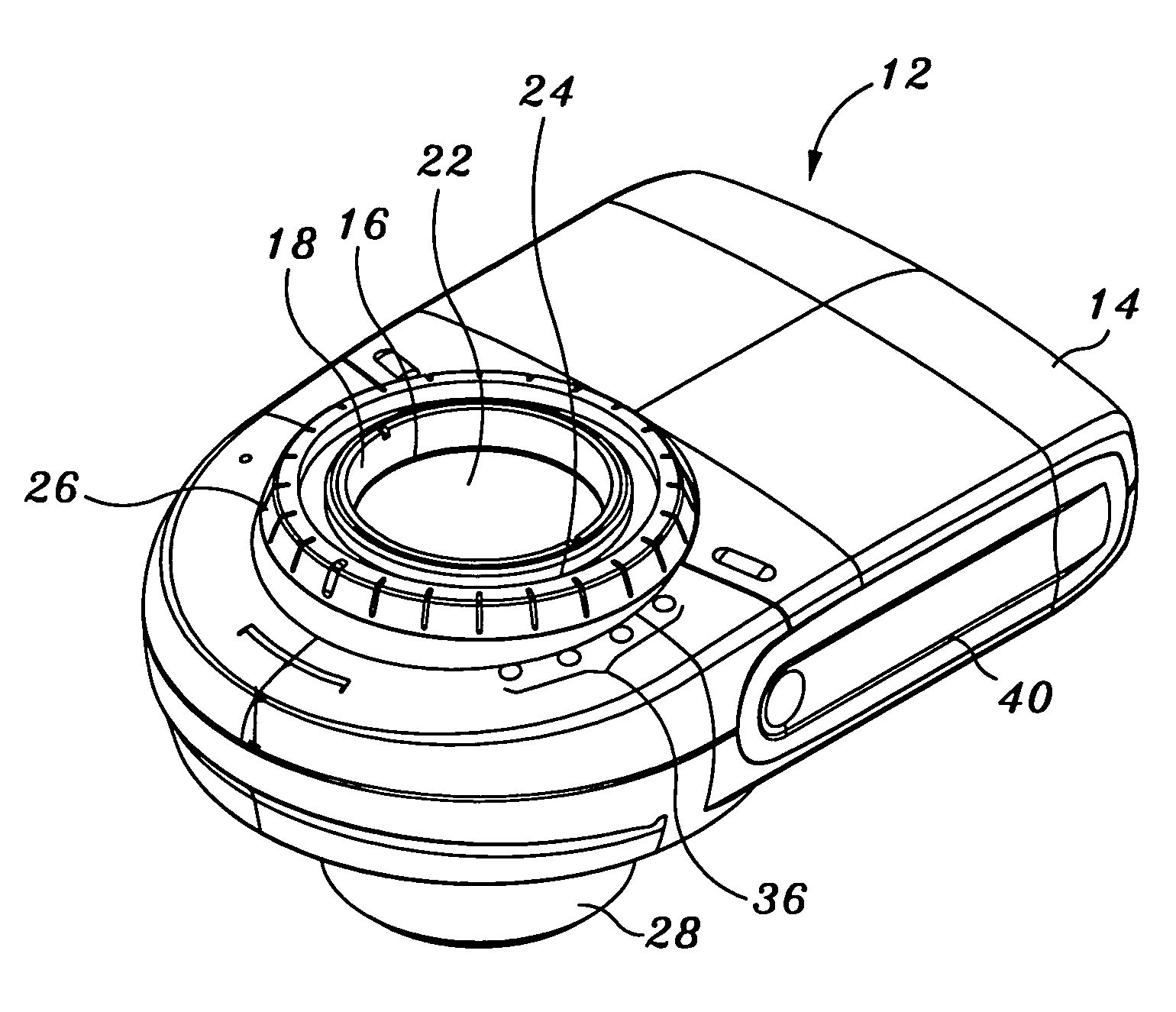
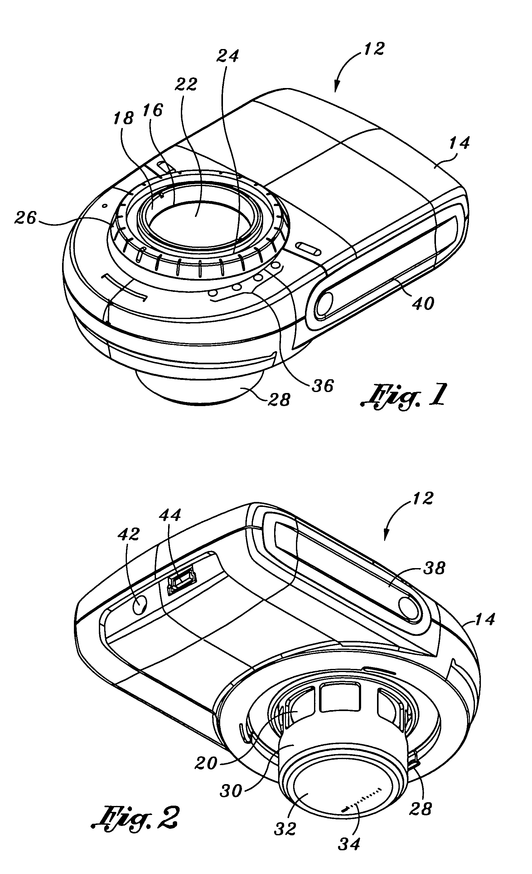
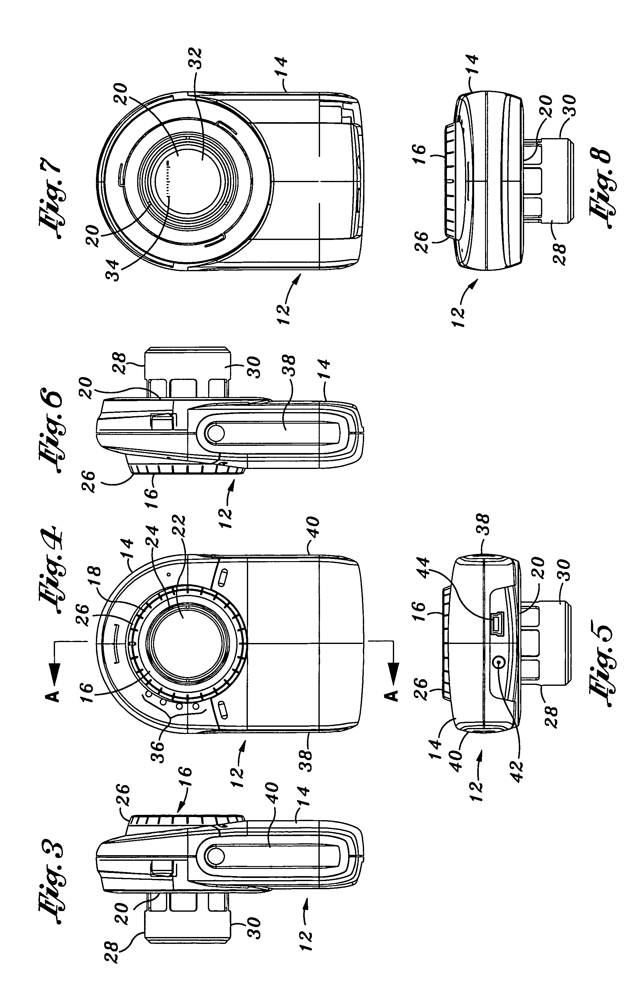
[0061]Referring particularly to FIGS. 9–11, the device of the present invention is shown. In FIG. 10 the device 12 is shown from a bottom perspective exploded view, and in FIG. 11 the device 12 is shown from a top perspective exploded view. The housing 14 is formed from top housing component 14a and bottom housing component 14b. Both components 14a and 14b include apertures for receiving a lens assembly 50, and accommodating a lighting array 46. The lighting array comprises a ring of LEDs affixed to an circuit board 48. The circuit board 48 is secured within the housing 14. The LEDs comprise four different colored sets of LEDs each on a different lighting circuit. The four colors comprise White, UV / Blue (405 nm), green / yellow (565 nm) and orange / red (630 nm). White is contemplated for normal epiluminescence imaging, U / Blue for ALA florescence and autoflouresence imaging an, green / yellow for superficial blood vessel imaging and orange / red for deeper blood vessel imaging. Although the...

second embodiment

[0070]Thirty two light emitting diodes of the array 46 ring the circuit board. The diodes are preferably white high light output Indium Gallium Nitride LEDs, however any suitable lighting diodes are appropriate. The even diodes are on a single circuit and the odd diodes are on a separate single circuit. In the second embodiment, the LEDs are a standard white LED made with phosphorescence phosphors to create white light. It is additionally contemplated by the present invention that tri-colored LEDs, with individual red, green and blue LEDs that can combine form white light may be utilized. It is contemplated by the present invention that the LEDs may have focusing lenses to concentrate the light into a smaller and tighter beam. The LEDs may additionally be comprised of indium gallium arsenide material, or any other like semiconductor material. A switch may initiates half of the every other light source, which are the eight even diodes and the switch also initiates the second light so...


PUM

PropertyMeasurementUnit
sizeaaaaaaaaaa
sizeaaaaaaaaaa
diameteraaaaaaaaaa

Abstract

The present invention provides a hand held dermoscopy epiluminescense device having a generally circular optical magnification lens incorporated into the housing of the device. A lighting array provides the light necessary for medical examination of the skin. The lighting array comprises a ring of LEDs comprising four different colored sets of LEDs each on a different lighting circuit. The four colors comprise White, UV / Blue (405 nm), green / yellow (565 nm) and orange / red (630 nm). A second embodiment provides a hand held dermoscopy epiluminescense device with a magnification lens and an associated ring of luminous diodes powered by an on board battery. Every other diode in the ring operates as first and second light sources. The even diodes are filtered by a first polarization ring and the odd diodes are filtered by a second polarization ring. Each polarization ring has an open center for the lens and openings sized and positioned to correspond to the even or odd diodes to only filter one set. A viewing polarizer is provided and is cross-polarized relative to the first polarization ring and is parallel-polarized with the second polarization ring. The device is threaded to mate with a camera or camera lens.

Description

CROSS-REFERENCE TO RELATED APPLICATIONS[0001]The present application is a continuation-in-part of U.S. patent application Ser. No. 10 / 384,110 filed Mar. 7, 2003 entitled Dermoscopy Epiluminescence Device Employing Cross and Parallel Polarization, the substance of which is relied upon and incorporated herein by reference.STATEMENT RE: FEDERALLY SPONSORED RESEARCH / DEVELOPMENT[0002]Not Applicable.FIELD OF THE INVENTION[0003]The present invention relates generally to an epiluminescence device used in dermoscopy. More particularly, the invention comprises an improved apparatus for illuminating the skin for medical examination by providing multiple colored light sources to aid in viewing and treatment of the skin.BACKGROUND OF THE INVENTION[0004]Dermoscopy is the term used to describe methods of imaging skin lesions. Skin is the largest organ in the body and it is the most easily accessible organ for external optical imaging. For early detection of cancers, it is important that the skin b...

Claims


Application Information

Patent Timeline
Patent Type & Authority Patents(United States)
IPC IPC(8): G01J4/00A61B5/103G01N21/64
CPCA61B5/0059A61B5/444G01N21/6447G01N21/6445A61B5/445G01N21/6458
Inventor MULLANI, NIZAR A.
Owner DERMLITE LLC
Why Eureka
Try Eureka