Delay locked loop (DLL) in semiconductor device

a technology of delay locking and semiconductor devices, applied in the field of semiconductor devices, can solve the problems of time delay generation, inability to obtain desired internal clocks, and long time to achieve delay locking in a low frequency

Inactive Publication Date: 2006-04-11
SK HYNIX INC
View PDF19 Cites 24 Cited by
  • Summary
  • Abstract
  • Description
  • Claims
  • Application Information

AI Technical Summary

Benefits of technology

[0019]It is, therefore, an object of the present invention to provide a delay locked loop (DLL) circuit having a variable clock divider to be applied to high and low frequencies.

Problems solved by technology

At this time, a time delay is generated when the clock signal provided from the external circuit is used in an internal circuit.
However, since the delay lines 16 to 163 cannot be initially shift left, a desired internal clock cannot be obtained.
However, if the conventional DLL circuit having the ⅛ clock divider is used, the DLL circuit cannot be used for the high frequency, and, if the convention DLL circuit having the 2 / 8 clock divider is used, since the reference signal has a pulse width of 2 tck, there is a problem that it takes a long time to achieve a delay locking in a low frequency due to a long rising time difference between the reference signal and the feedback signal Feedback.
Also, if the 2 / 8 clock divider is used in a low frequency, since it causes that the number of unit delays have to be increased so as to achieve a delay locking, there is a problem that a layout area of the DLL circuit is increased.

Method used


Image

  • Delay locked loop (DLL) in semiconductor device
  • Delay locked loop (DLL) in semiconductor device
  • Delay locked loop (DLL) in semiconductor device

Examples


Embodiment Construction

[0033]Hereinafter, a DLL circuit having a controller for selecting a divider suitable for a random frequency according to the present invention will be described in detail referring to the accompanying drawings.

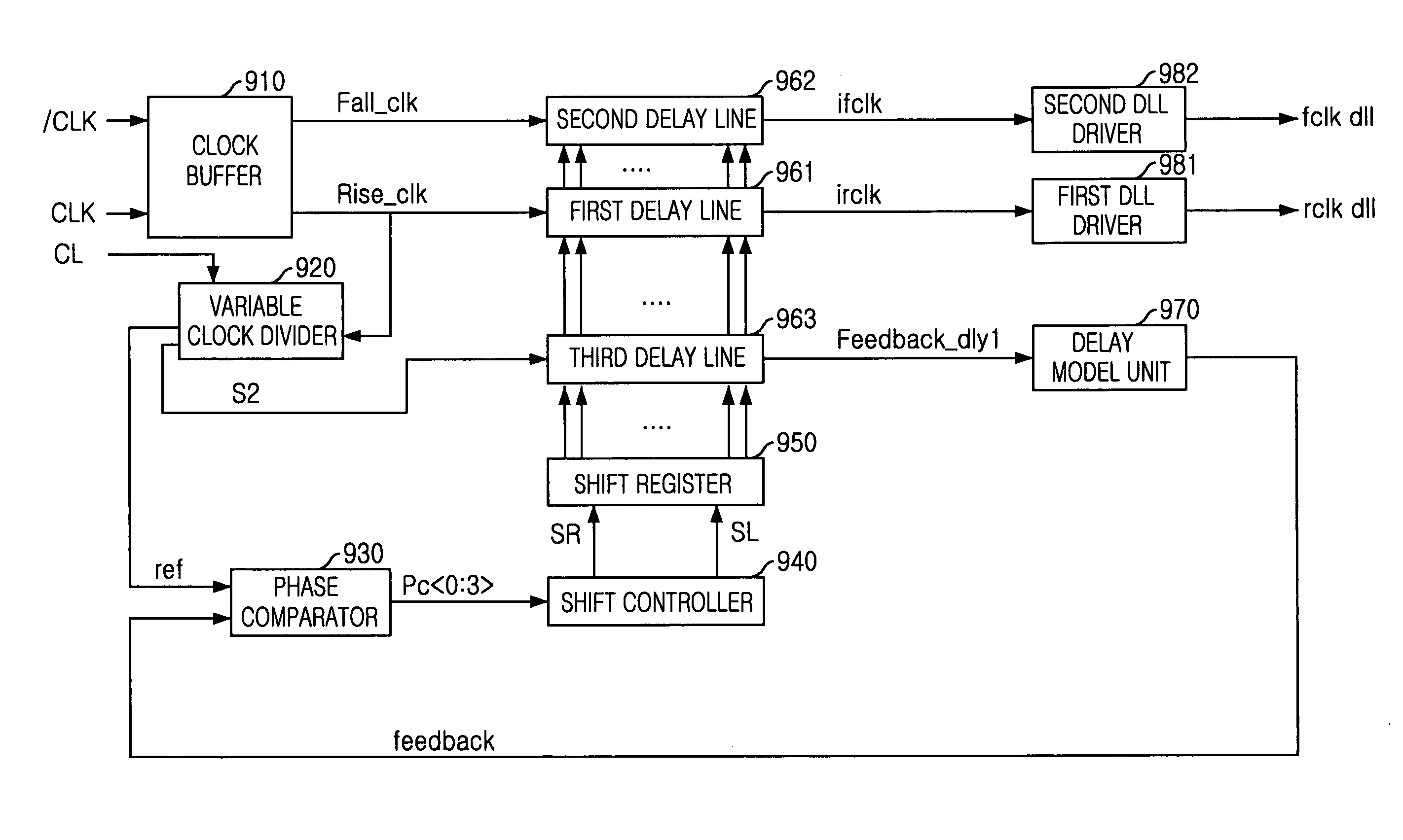
[0034]FIG. 9 is a block diagram illustrating a DLL circuit in accordance with the preferred embodiment of the present invention. The DLL circuit includes a clock buffer 910, a variable clock divider 920, a phase comparator 930, a shift controller 940, a shift register 950, a plurality of delay lines 961, 962 and 963, a delay model unit 970 and a plurality of DLL drivers 981 and 982.

[0035]The clock buffer 910 receives an external clock signal and an inverted clock signal CLK and / CLK and outputs internal clock signals Fall_clk and Rise_clk.

[0036]The variable clock divider 920 receives the internal clock signal Rise_clk and a control signal CL based on a column address strobe (CAS) latency, which is set according to a frequency of the external clock signal, wherein the control ...


PUM


Abstract

A delay locked loop (DLL) in a semiconductor device, includes an clock buffer receiving an external clock signal and an inverted clock signal and outputting first and second internal clock signals to be used in the DLL circuit; and a variable clock divider receiving the second internal signal from the clock buffer and variably dividing the second internal clock signal to have a predetermined pulse width according to a control signal based on a column address strobe (CAS) latency, which is set according to a frequency of the external clock signal, wherein the control signal is initially set to have a first logic level and is enabled to a second logic level when the CAS latency corresponds to a high frequency.

Description

FIELD OF THE INVENTION[0001]The present invention relates to a semiconductor device; and, more particularly, to a delay locked loop having a variable clock divider to be applied to high and low frequencies by using a column address strobe (CAS) latency in the semiconductor device.DESCRIPTION OF RELATED ART[0002]Generally, a clock signal is employed to set a timing reference and secure a rapid operation without any error in a system or a circuit. At this time, a time delay is generated when the clock signal provided from the external circuit is used in an internal circuit. The time delay is adjusted by a delay locked loop (DLL) circuit to have an identical phase between the external clock signal and the internal clock signal.[0003]FIG. 1 is a block diagram illustrating a conventional DLL circuit. The DLL circuit includes a clock buffer 110, a clock divider 120, a phase comparator 130, a shift controller 140, a shift register 150, a plurality of delay lines 161, 162 and 163, a delay m...

Claims


Application Information

Patent Timeline
Patent Type & Authority Patents(United States)
IPC IPC(8): G11C8/00H03L7/08H01L27/00H01L31/0328H03L7/081
CPCH03L7/0814H03L7/0805H03L7/0816H03L7/08
Inventor JUNG, HEA-SUK
Owner SK HYNIX INC
Why Eureka
Try Eureka