
System for booting distributed processor architecture by loading boot software via ethernet to sub-unit after main unit is booted and released the sub-unit from reset

a distributed processor and boot software technology, applied in the field of booting distributed processor architecture, can solve the problems of large consumption of printed board space, inability to connect non-volatile memories with identical boot codes to all sub-processors, and inability to meet the requirements of the sub-processor, so as to achieve the effect of less printed board space consumption, cost saving and faster manufacturing

Inactive Publication Date: 2006-04-11
CRYSTAL MOUNTAIN COMM LLC
View PDF12 Cites 8 Cited by
  • Summary
  • Abstract
  • Description
  • Claims
  • Application Information

AI Technical Summary

Benefits of technology

"The invention provides an improved method and device for a base station. The method involves booting the main unit of the base station and then using loaded boot software to boot the sub-unit. This reduces the number of components and printed board space required, saving costs. The manufacturing process is faster and more flexible, with the ability to use different manufacturers' components. The technical effects of the invention are improved efficiency and flexibility in the design and manufacturing of base stations."

Problems solved by technology

The disadvantage of the prior art solutions is that non-volatile memories with identical boot codes must be connected to all sub-processors.
Thus, more components are required and much printed board space is consumed.
Therefore, also costs are increased.
Further, when a printed board of a unit formed by the process architecture is manufactured, more solder joints are required, whereby also the manufacturing is slower and the sensitivity to failure and the failure density in the device increase.

Method used


Image

  • System for booting distributed processor architecture by loading boot software via ethernet to sub-unit after main unit is booted and released the sub-unit from reset
  • System for booting distributed processor architecture by loading boot software via ethernet to sub-unit after main unit is booted and released the sub-unit from reset
  • System for booting distributed processor architecture by loading boot software via ethernet to sub-unit after main unit is booted and released the sub-unit from reset

Examples


Embodiment Construction

[0014]A method and a device implementing the method can be used to boot distributed processor architecture of a base station in a radio system. The base station can be, for instance, a third-generation base station according to the UMTS system and applying WCDMA technology, or what is called a 2.5-generation GSM / EDGE or GSM / GPRS base station applying EDGE or GPRS technology, or a second-generation base station applying GSM technology. The base station can be, for instance, an IP-connected base station, where the Internet protocol can be used in data transmission both between units and between different blocks within a unit. The method can be used to boot either the whole base station or a unit thereof.

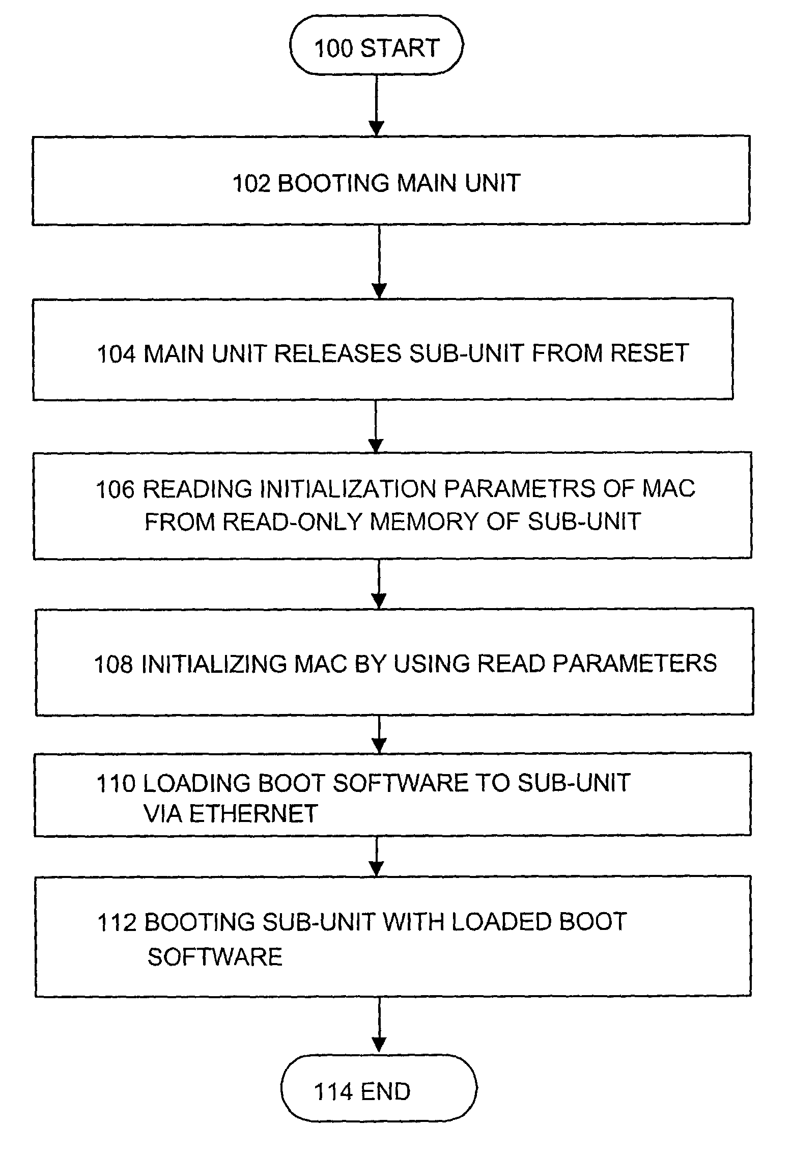
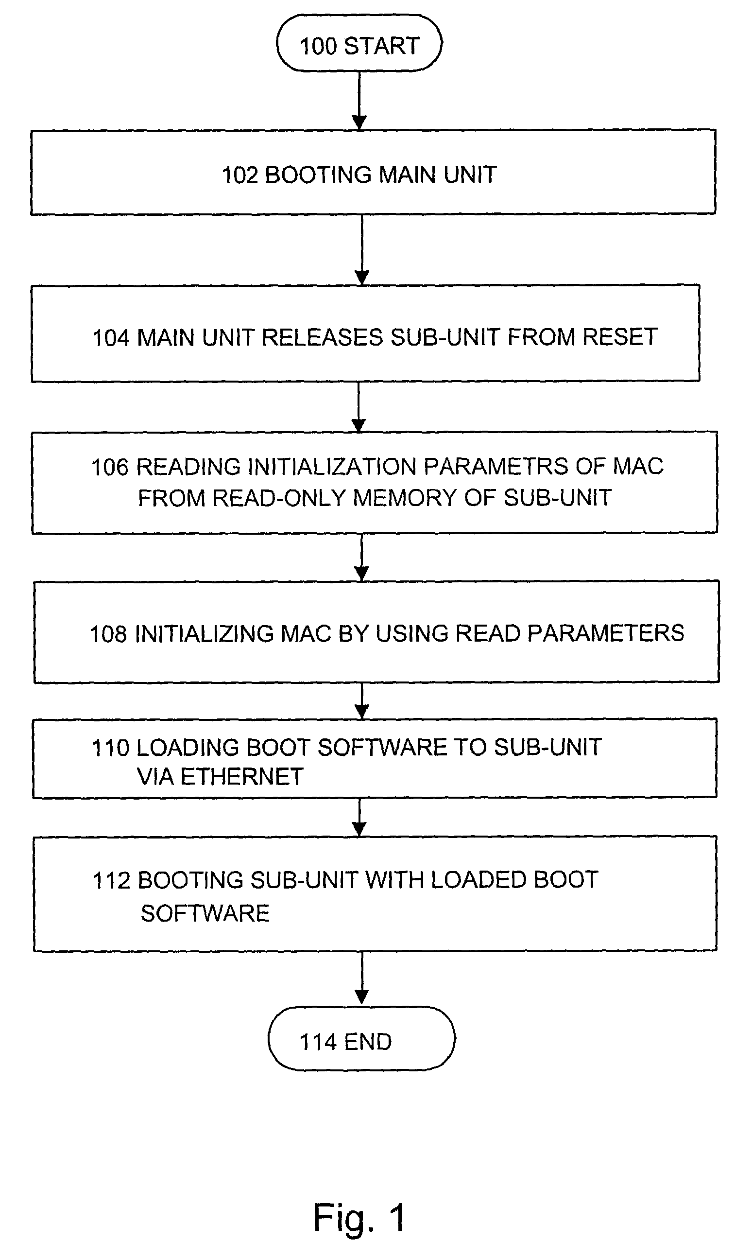
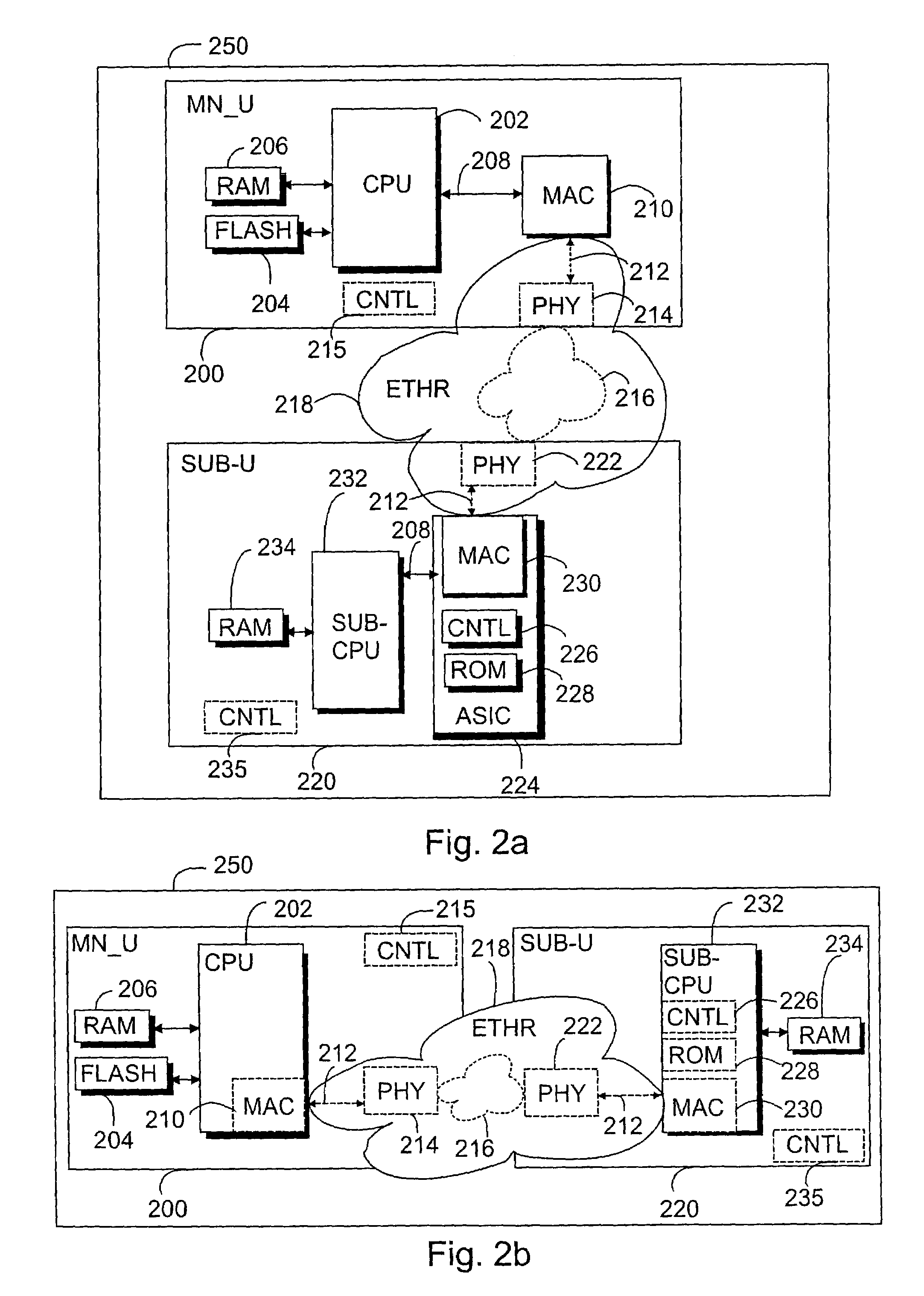
[0015]With reference to the flow chart according to FIG. 1 and to the simplified block diagram of FIGS. 2a and 2b, the method of booting distributed processor architecture of a base station is described. The distributed processor architecture comprises a main unit 200 and at least one ...


PUM


Abstract

The invention relates to a base station comprising distributed processor architecture and a method of booting distributed processor architecture of a base station. The distributed processor architecture of the base station comprises a main unit and at least one sub-unit connected to it via the Ethernet. In the method, the main unit is booted, which main unit releases the sub-unit from reset. The control logic of the sub-unit reads the initialization parameters of the MAC controller stored in the read-only memory of the sub-unit. The MAC controller is initialized by using the read initialization parameters, after which boot software is loaded to the sub-unit via the Ethernet. Finally, the sub-unit is booted with the loaded boot software.

Description

[0001]This is a continuation of Internation Application No. PCT / FI02 / 00766 filed Sep. 24, 2002, which designated the U.S. and was published under PCT Article 21(2) in English.FIELD[0002]The invention relates to a method of booting distributed processor architecture and to a base station.BACKGROUND[0003]Distributed processor architectures are in use in base stations of radio systems, both at the level of the whole base station and at the unit level. In distributed processor architectures, several processors can attend to similar tasks, such as in digital signal processing, where several digital signal processors are connected to each other. Sub-units of such distributed processor architectures can also contain other components, for instance memories and application-specific integrated circuits (ASIC).[0004]Usually, such sub-units connected to each other boot automatically. Each sub-unit and a processor in it can be booted independently, for instance by means of boot software stored i...

Claims


Application Information

Patent Timeline
Patent Type & Authority Patents(United States)
IPC IPC(8): G06F15/177G06F1/24G06F9/445H04W88/08
CPCG06F9/4416H04W88/08
Inventor ASPEGREN, SAMIVIERO, TIMOHEIKKINEN, EERO
Owner CRYSTAL MOUNTAIN COMM LLC
Learn More