Method of producing an ink jet recording head

a technology of ink jet and recording head, which is applied in the direction of recording equipment, recording information storage, instruments, etc., can solve the problems of affecting the efficiency of the assembling step, the disadvantageous degradation of the rigidity of the spacer, and the distortion of the passage unit having a relatively low rigidity, so as to reduce the effective volume of the pressurizing chamber and reduce the ratio of through holes. , the effect of reducing the effective volume of the ejection of ink drops

Inactive Publication Date: 2006-04-18
SEIKO EPSON CORP
View PDF43 Cites 6 Cited by
  • Summary
  • Abstract
  • Description
  • Claims
  • Application Information

AI Technical Summary

Benefits of technology

[0016]The invention provides an ink jet recording head comprising: a spacer in which pressurizing chambers, an ink supply port, and a common ink chamber are formed by anisotropic etching of a silicon single-crystal substrate; a nozzle plate having nozzle openings at the same pitches as those of the pressurizing chambers; and an elastic plate which causes the pressurizing chambers to expand and contract, the nozzle plate being attached to one face of the spacer, the elastic plates being attached to the other face of the spacer. In the ink jet recording head, the pressurizing chambers are formed as recesses by half etching of the silicon single-crystal substrate, and nozzle communicating holes through which the pressurizing chambers are connected to the nozzle openings are formed as through holes each having a size smaller than a width of each of the pressurizing chambers, by full etching of the silicon single-crystal substrate. The common ink chamber is formed as a through hole by full etching of the silicon single-crystal substrate. Since each of the pressurizing chambers is formed as a recess, the volume of the pressurizing chamber is reduced to a degree as small as possible. Each of the pressurizing chambers is connected to the corresponding nozzle opening on the other face side via the nozzle communicating hole, so that the effective volume related to the ejection of ink drops is reduced. The ratio occupied by through holes is reduced so that the inherent rigidity of the silicon single-crystal substrate is effectively used.

Problems solved by technology

This produces a problem in that damages or unpredictable warpage may disadvantageously occur in the assembling step.
Accordingly, there arises a problem in that the opening area of the silicon single-crystal substrate is increased and eventually the rigidity of the spacer is disadvantageously degraded.
Although such a damage may not be caused, the passage unit having a relatively low rigidity is distorted by the stress caused by the difference in thermal expansion.
As a result, there arises a problem in that the flying directions of ink drops go out of alignment and errors are caused in hitting positions, thereby degrading the printing quality.

Method used


Image

  • Method of producing an ink jet recording head
  • Method of producing an ink jet recording head
  • Method of producing an ink jet recording head

Examples


Embodiment Construction

[0045]Hereinafter, embodiments of the invention shown in the figures will be described in detail.

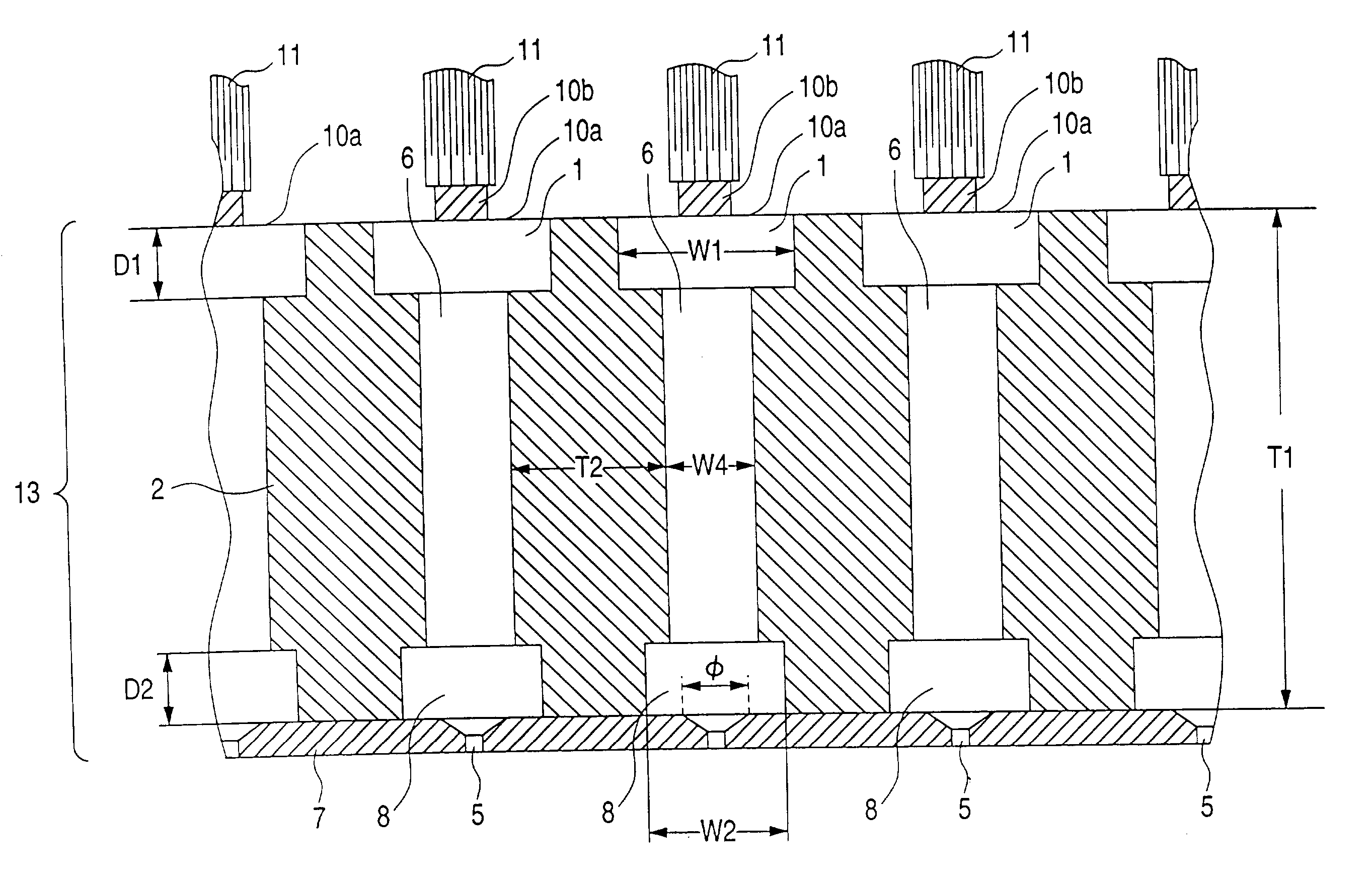
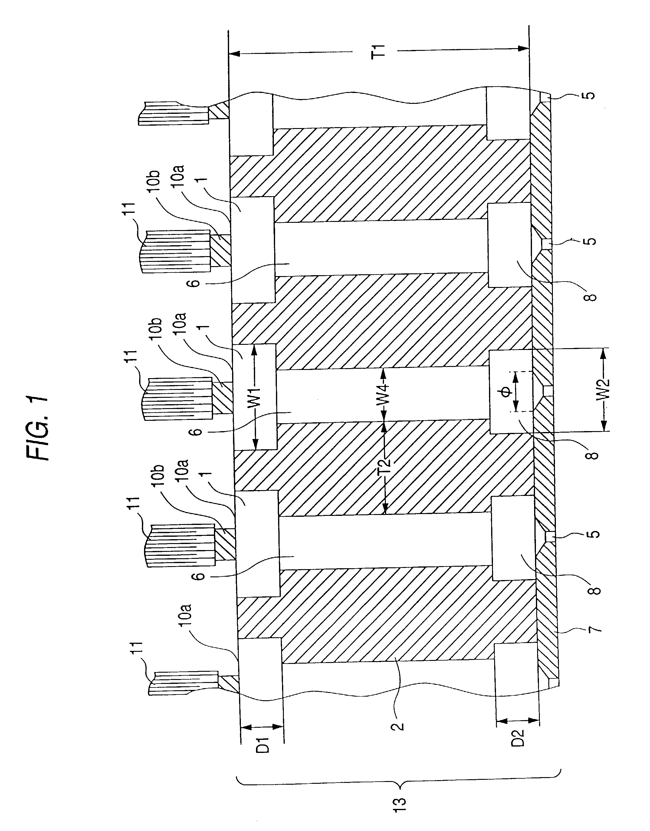
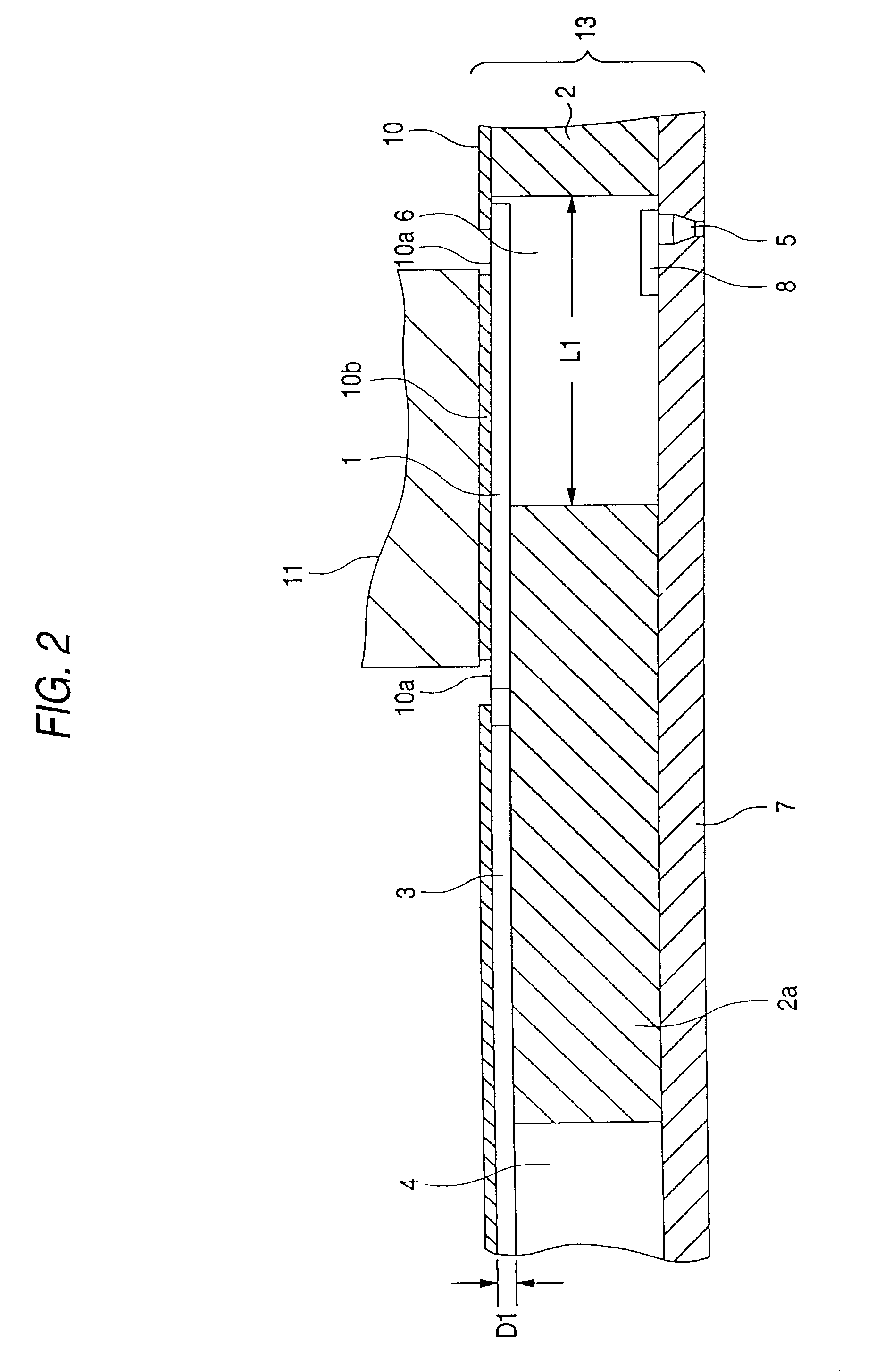
[0046]FIGS. 1 and 2 show an embodiment of the invention in a section structure in the vicinity of pressurizing chambers 1. FIG. 3 shows a top structure of a spacer 2 according to the present invention. The spacer 2 is formed by subjecting anisotropic etching on a silicon single-crystal substrate used as a base material, having the surface of a predetermined crystal orientation, for example, a crystal orientation (110). On one face, formed are the pressurizing chamber 1 having a depth D1 which is smaller than the thickness T1 of the silicon single-crystal substrate constituting the spacer 2, and an ink supply port 3.

[0047]A common ink chamber 4 is formed as a through hole so as to be communicated with the ink supply port 3. On one end of the pressurizing chamber 1, a nozzle communicating hole 6 is formed for connecting the pressurizing chamber 1 to a nozzle opening 5. In order to increase...


PUM

PropertyMeasurementUnit
thicknessaaaaaaaaaa
lengthaaaaaaaaaa
thicknessaaaaaaaaaa

Abstract

A method of producing an ink jet recording head, which includes (1) fixing a passage unit in which a nozzle pate having a nozzle opening, a spacer forming a common ink chamber, and an elastic plate having a thick portion abutting against an end of a piezoelectric vibrating element are stacked, to an opening of a frame having an overhang portion which overhangs to a vicinity of the thick portion, (2) inserting a vibrating element unit into the frame, the vibrating element unit being configured by fixing piezoelectric vibrating elements operating in a longitudinal vibration mode to a fixing substrate, and (3) injecting an adhesive into a groove formed in a region opposing the fixing substrate of the frame.

Description

[0001]This is a division of application Ser. No. 09 / 576,174 filed May 23, 2000 now U.S. Pat. No. 6,729,002, which is a division of application Ser. No. 08 / 708,675 filed Sep. 5, 1996 now U.S. Pat. No. 6,139,132, the disclosures of which are incorporated herein by reference.BACKGROUND OF THE INVENTION[0002]The invention relates to an ink jet recording head in which a silicon single-crystal substrate is used for a spacer forming member, and a method of producing such an ink jet recording head.[0003]An ink jet recording head has a pressurizing chamber formed by respectively attaching a nozzle plate in which nozzle openings are formed and an elastic plate to both faces of a spacer with an adhesive. The elastic plate is deformed by a piezoelectric vibrating element. Since the ink jet recording head of this type does not utilize a thermal energy as a driving source for ejecting ink drops, the ink quality is not thermally changed. Particularly, therefore, it is available to eject color inks...

Claims


Application Information

Patent Timeline
Patent Type & Authority Patents(United States)
IPC IPC(8): H04R17/00B41J2/045C09J5/00B41J2/14B41J2/16
CPCB41J2/14274B41J2/1612B41J2/1623B41J2/1629B41J2/1634Y10T29/49156B41J2002/14387B41J2002/14419Y10T29/49401Y10T29/42
Inventor YASUKAWA, SHINJIUSUI, MINORUNAKA, TAKAHIROKITAHARA, TSUYOSHIOKAZAWA, NORIAKISONEHARA, HIDEAKI
Owner SEIKO EPSON CORP
Why Eureka
Try Eureka