
Quasi resonant gate controller for a power driver

a power driver and resonant gate technology, applied in electrical control, non-mechanical valves, pulse techniques, etc., can solve the problems of camlobe wear, engine efficiency decline, wear typically increases,

Inactive Publication Date: 2006-04-18
CONTINENTAL AUTOMOTIVE SYST INC
View PDF1 Cites 8 Cited by
  • Summary
  • Abstract
  • Description
  • Claims
  • Application Information

AI Technical Summary

Benefits of technology

The present invention relates to a new type of gate controller for a power driver that uses a qui resonant gate controller for a power driver. This new type of gate controller can improve engine efficiency, decrease emissions, and improve driveability. The invention is based on the use of electromechanically or electrohydraulically actuated valves, which can be controlled electronically to achieve precise timing and improve fuel economy, emissions reduction, and reliability. The invention can also programmed to shut down or ski fire one or more of the engine's cylinders when not needed to save fuel and reduce emissions. Overall, the invention provides a new way to improve the performance and efficiency of engines.

Problems solved by technology

Furthermore, the camlobes are subject to wear, and such wear typically increases as the energy required to open the valves increases.
Because worn camlobes adversely affect the opening and closing of the valves, the efficiency of the engine typically decreases and the emissions from the engine increase.
Commercially available ECMs have been limited generally to fuel and spark controls.
However, the mass and inertia of such vehicles is much larger than that of a passenger car, thus requiring powerful braking mechanisms to enable the driver of an on-highway truck to decelerate safely.
As can be appreciated, compression brakes typically include complex mechanisms that must be added to the engine to control the valves during the braking process.
However, the power consumption, cost, size, and packaging requirements of existing electrically actuated engine valves and their corresponding control circuits have prevented such designs from becoming commercially feasible.
From this simple calculation, it can be seen that size and efficiency quickly becomes an issue.
As can be appreciated, such liquid cooling solutions introduce additional size and complexity into the packaging requirements of the control and add cost as well.

Method used


Image

  • Quasi resonant gate controller for a power driver
  • Quasi resonant gate controller for a power driver
  • Quasi resonant gate controller for a power driver

Examples


Embodiment Construction

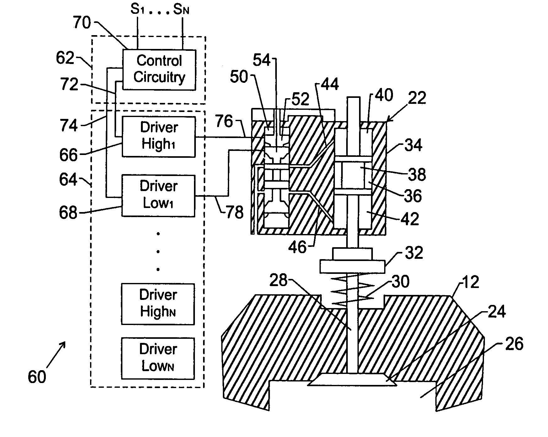
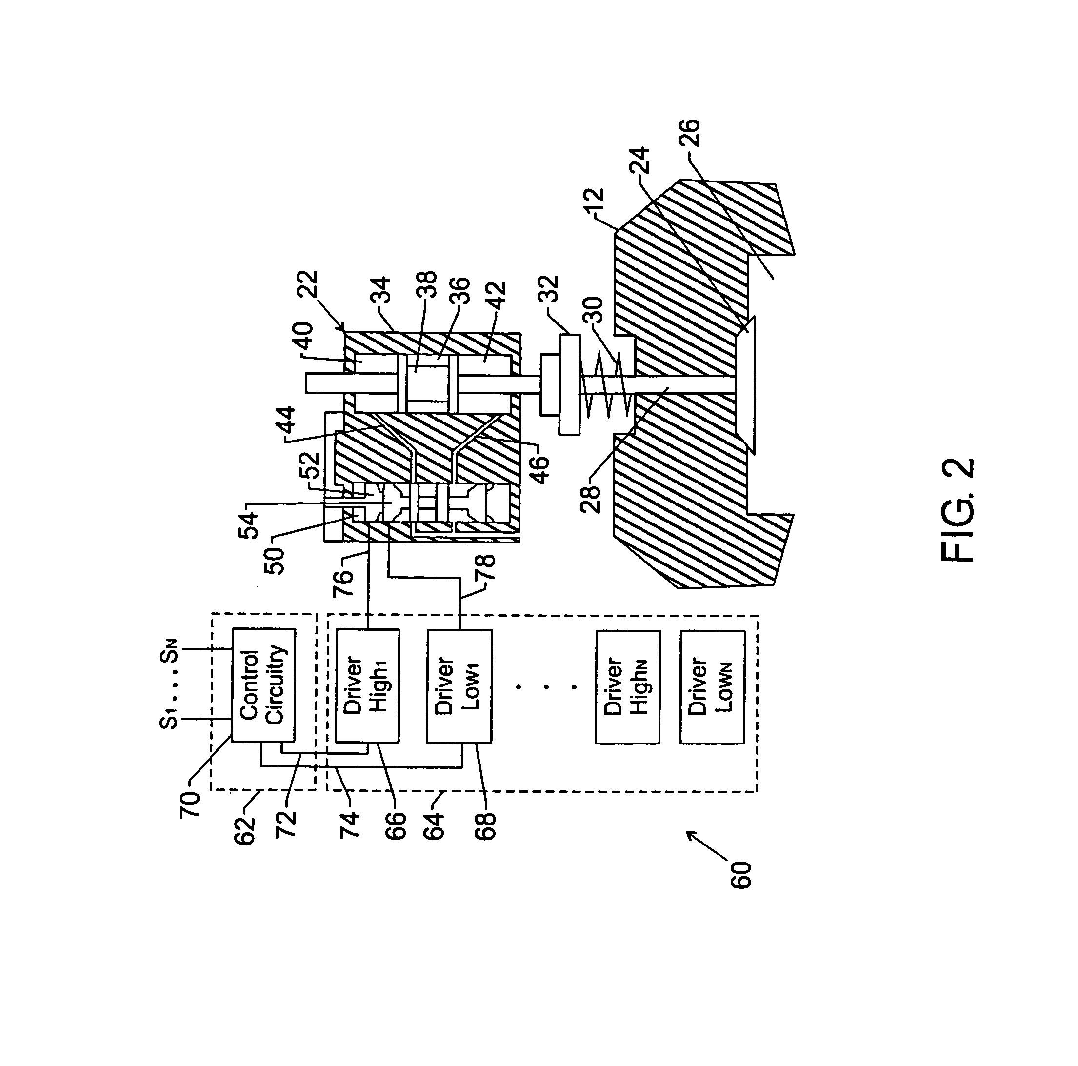
[0020]One or more specific embodiments of the present invention will be described below. In an effort to provide a concise description of these embodiments, not all features of an actual implementation are described in the specification. It should be appreciated that in the development of any such actual implementation, as in any engineering or design project, numerous implementation-specific decisions must be made to achieve the developers' specific goals, such as compliance with system-related and business-related constraints, which may vary from one implementation to another. Moreover, it should be appreciated that such a development effort might be complex and time consuming, but would nevertheless be a routine undertaking of design, fabrication, and manufacture for those of ordinary skill having the benefit of this disclosure.

[0021]One of the primary issues that exist in turning on and off a power transistor, such as a power MOSFET, is the losses that occur during transition fr...


PUM


Abstract

A drive circuit for a power device includes a power transistor utilized to drive the power device. The drive circuit utilizes a resonant circuit that drives the power transistor at a high current level when the gate of the power transistor is in its Miller region. In one embodiment, the drive circuit includes dual transistors and an inductor tuned to the gate capacitance to drive the gate of the power transistor. The drive circuit may be useful in a variety of areas, such as with a valve controller for a camless engine.

Description

FIELD OF THE INVENTION[0001]The present invention relates to generally to gate controllers and, more particularly, to a quasi resonant gate controller for a power driver.BACKGROUND INFORMATION[0002]This section is intended to introduce the reader to various aspects of art that may be related to various aspects of the present invention, which are described and / or claimed below. This discussion is believed to be helpful in providing the reader with background information to facilitate a better understanding of the various aspects of the present invention. Accordingly, it should be understood that these statements are to be read in this light, and not as admissions of prior art.[0003]Historically, mechanical systems that require great forces to actuate their moving parts have utilized mechanical and / or hydraulic actuators. As one example, an internal combustion engine contains at least one intake valve and at least one exhaust valve for each cylinder of the engine. As is well known, th...

Claims


Application Information

Patent Timeline
Patent Type & Authority Patents(United States)
IPC IPC(8): F01L9/04F01L9/10F01L9/16F01L9/20
CPCF01L9/02F01L9/026F02D41/20H03K17/6871F01L9/04Y02T10/142Y02T10/12F01L9/16F01L9/10F01L9/20
Inventor MERWIN, JEFFREY D.
Owner CONTINENTAL AUTOMOTIVE SYST INC
Learn More