Radiation-heated fluidized-bed reactor

a fluidized-bed reactor and radiation-heated technology, applied in the direction of furnaces, lighting and heating apparatus, silicon compounds, etc., can solve the problem that other heating methods than microwave heating were in fact excluded, and achieve the effect of low agglomeration and high purity

Inactive Publication Date: 2006-04-18
WACKER CHEM GMBH
View PDF8 Cites 156 Cited by
  • Summary
  • Abstract
  • Description
  • Claims
  • Application Information

AI Technical Summary

Benefits of technology

[0021]It is an object of the present invention to provide a fluidized-bed reactor in which the fluidized bed is heated in such a manner that it can be opera

Problems solved by technology

In that document, very much to the contrary, heating methods other than microwave heating were in fact r

Method used


Image

  • Radiation-heated fluidized-bed reactor
  • Radiation-heated fluidized-bed reactor
  • Radiation-heated fluidized-bed reactor

Examples


invention

EXAMPLES (INVENTION)

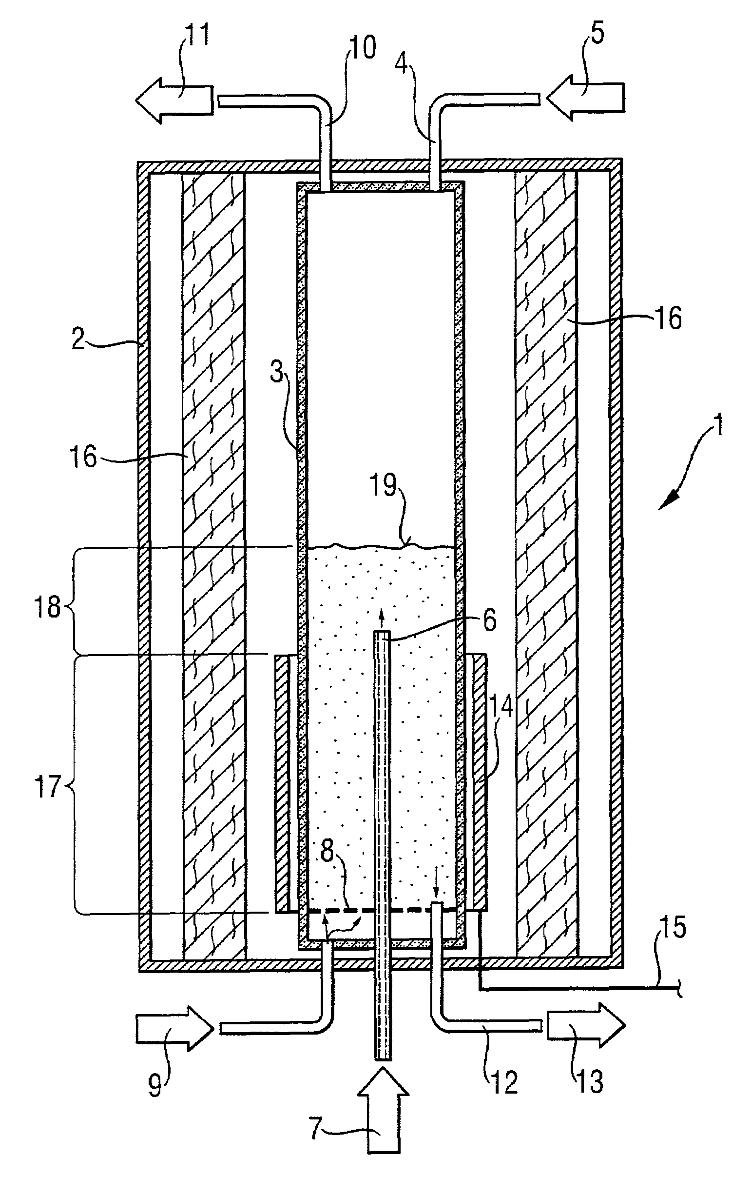
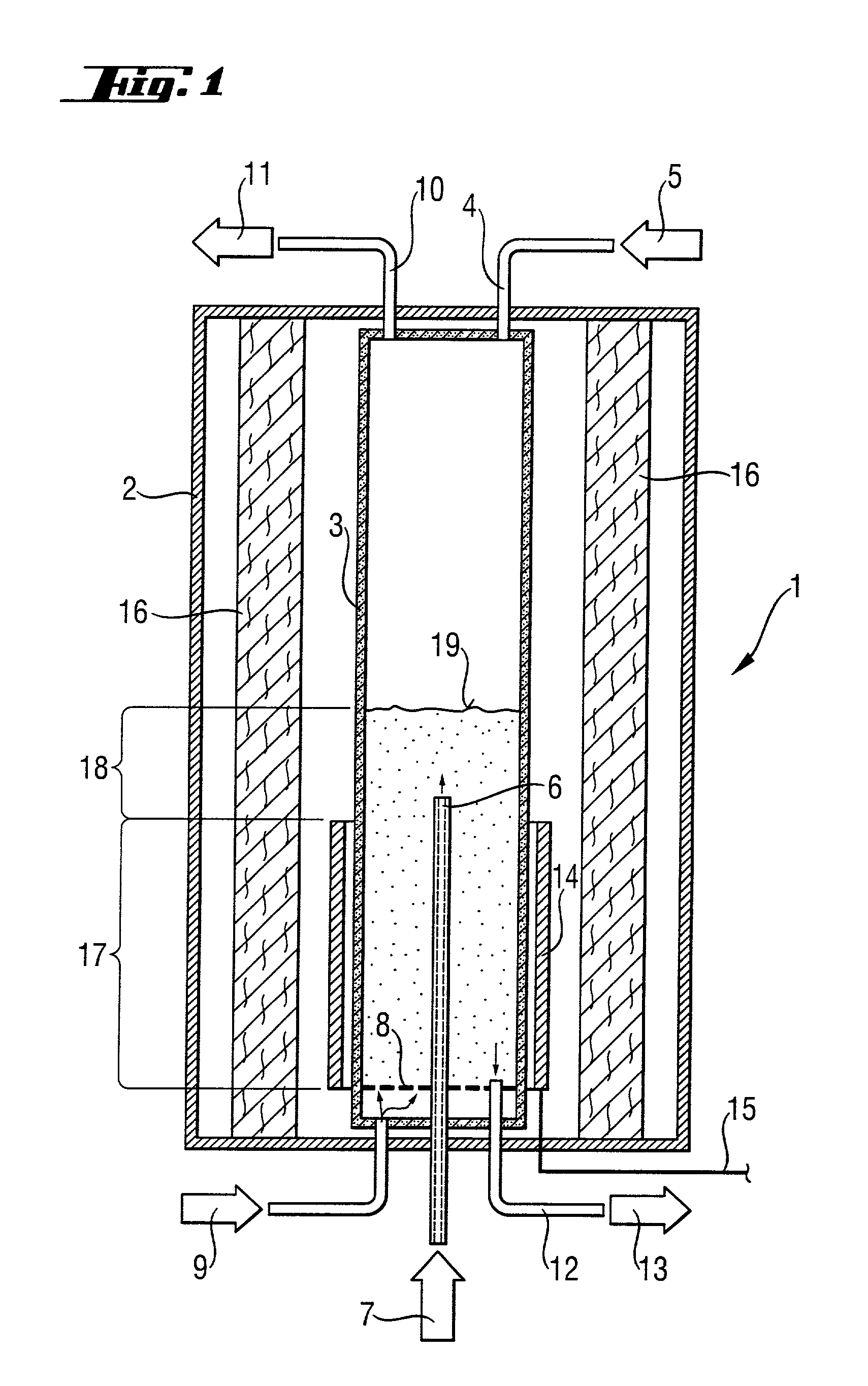
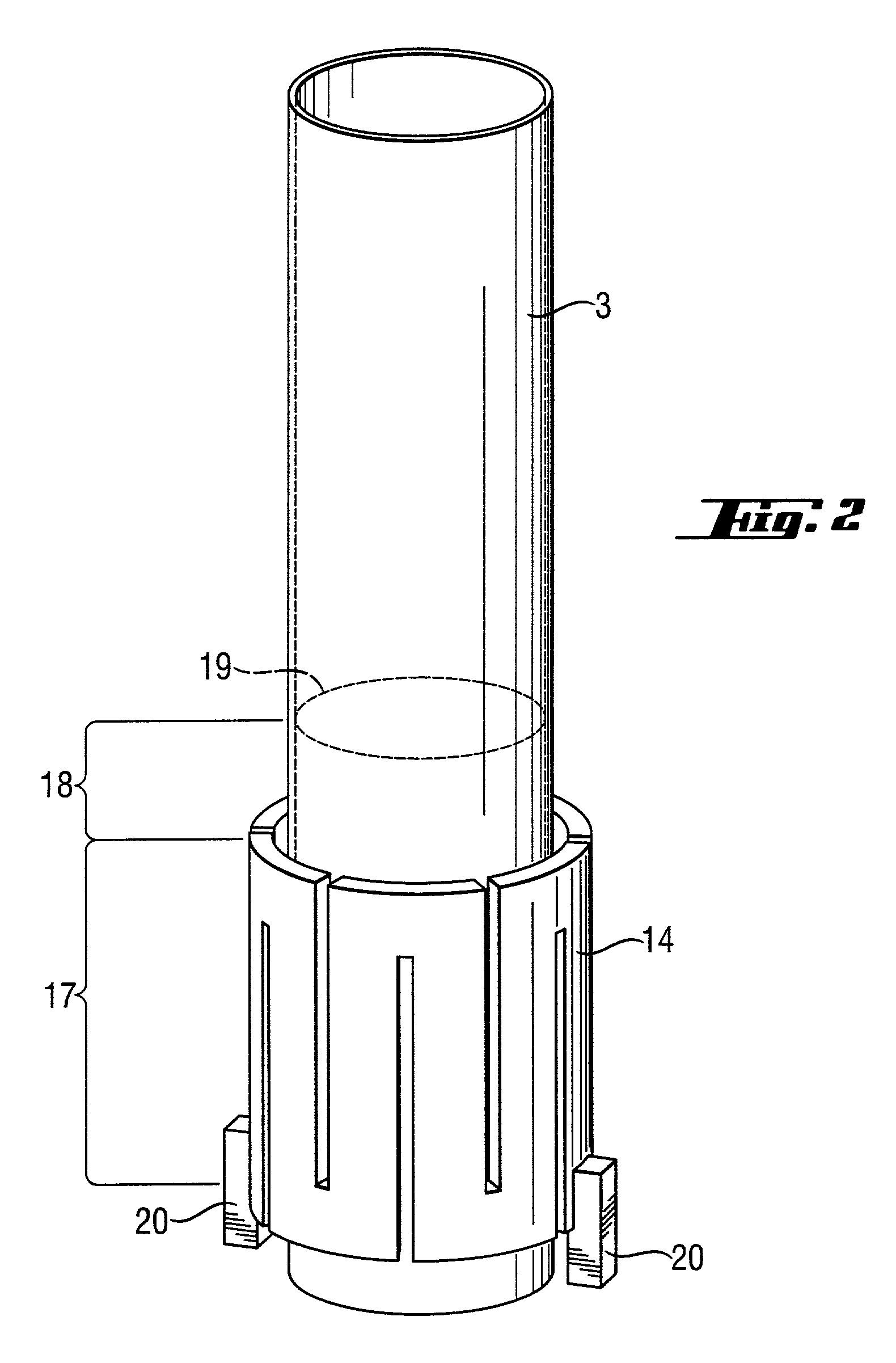
[0088]The reactor was rebuilt for the following tests. Instead of the microwave heating, a radiant heater was fitted as the source of thermal radiation. This heater was a tube with meandering slits made from graphite with a SiC surface coating, which surrounded the inner reactor tube in the region of the heating zone without coming into contact with the latter. The radiant heater was supplied with electric power via a controllable voltage source. Its maximum output was 40 kW.

example 1

[0089]The procedure was similar to Comparative Example 1. The starting fill was once again 24 kg.

[0090]The following conditions were established:

[0091]

Fluidizing gas hydrogen13.5 m3 / h (s.t.p.)Fluidizing gas inlet temperature120° C.No reaction gas addedTemperature of the reaction zone:920° C.Pressure in the reaction zone:1250 kPa (absolute)Heating capacity:12.5 kW

[0092]As in Example 1, the fluidized bed was operated for 24 hours at approx. 1.5 times the fluidization velocity unf. The grain size analysis of the particles which were then removed revealed a mean grain diameter of 565 μm. No sintered-together agglomerates were found. The inner side of the reactor tube was completely free of deposits.

example 2

[0093]In this example, it was demonstrated that the process is suitable for the production of high-purity silicon. For this purpose, the arrangement with the radiant heater was used once again. The inner reactor tube was filled with 28 kg of silicon particles, once again with a mean grain size of 550 μm.

[0094]The following conditions were established:

[0095]

Fluidizing gas: hydrogen27 m3 / h (s.t.p.)Reaction gas:Trichlorosilane30 kg / hHydrogen3.6 m3 / h (s.t.p.)Inlet temperature of the gases:120°Temperature of the reaction zone:920° C.Pressure in the reaction zone:1250 kPa (absolute)Net energy demand:37.5 kWAddition of silicon particles (250 μm)0.05 kg / h

[0096]The reactor was operated for 7 days at this setting. Product was removed every half hour, resulting in a mean production rate of 1.27 kg / h. The mean diameter of the product was 780 μm, and the product was free of agglomerates. After the end of the test, the inner side of the reactor tube in the region of the heating zone was completel...


PUM


Abstract

A radiation-heated fluidized-bed reactor and a process for producing high-purity polycrystalline silicon by using this reactor are provided. In this reactor, a heater device (14) is a radiation source for thermal radiation which is arranged outside the inner reactor tube and as a cylinder around the heater zone, without being in direct contact with the inner reactor tube. The inner reactor tube is designed in such a manner that it uses thermal radiation to heat the silicon particles in the heating zone to a temperature which is such that the reaction temperature is established in the reaction zone.

Description

BACKGROUND OF THE INVENTION[0001]1. Field of the Invention[0002]The present invention relates to a radiation-heated fluidized-bed reactor and to a process for producing high-purity polycrystalline silicon by means of this reactor.[0003]2. The Prior Art[0004]High-purity polycrystalline silicon is used, inter alia, as a starting material for the production of electronic components and solar cells. It is obtained by thermal decomposition of a silicon-containing gas or a silicon-containing gas mixture. This process is known as chemical vapor deposition (CVD). This process is carried out on a large scale in so-called Siemens reactors.[0005]Recently, however, there have been wide-ranging efforts to utilize a fluidized-bed process as an alternative to the discontinuous Siemens process. In this case, a fluidized bed of silicon particles, for example approximately spherical particles with a diameter of 200 m–3000 μm is used. The particles are heated to the required deposition temperatures of...

Claims


Application Information

Patent Timeline
IPC IPC(8): B01J8/18B01J19/12B01J8/42C01B33/02C01B33/021C01B33/027
CPCB01J8/1818B01J8/1836C01B33/027B01J2208/00433B01J2208/00495B01J2208/00132
Inventor WEIDHAUS, DIETERHAYDUK, ALEXANDER
Owner WACKER CHEM GMBH
Why Eureka
Try Eureka