Semiconductor device fabrication method
a technology of semiconductor devices and fabrication methods, applied in semiconductor/solid-state device manufacturing, basic electric elements, electric devices, etc., can solve the problems of lowering process yield and uneven transistor characteristics, and achieve the effect of preventing the occurrence of silicon layer dishing and improving process yield
- Summary
- Abstract
- Description
- Claims
- Application Information
AI Technical Summary
Benefits of technology
Problems solved by technology
Method used
Image
Examples
first embodiment
1. First Embodiment
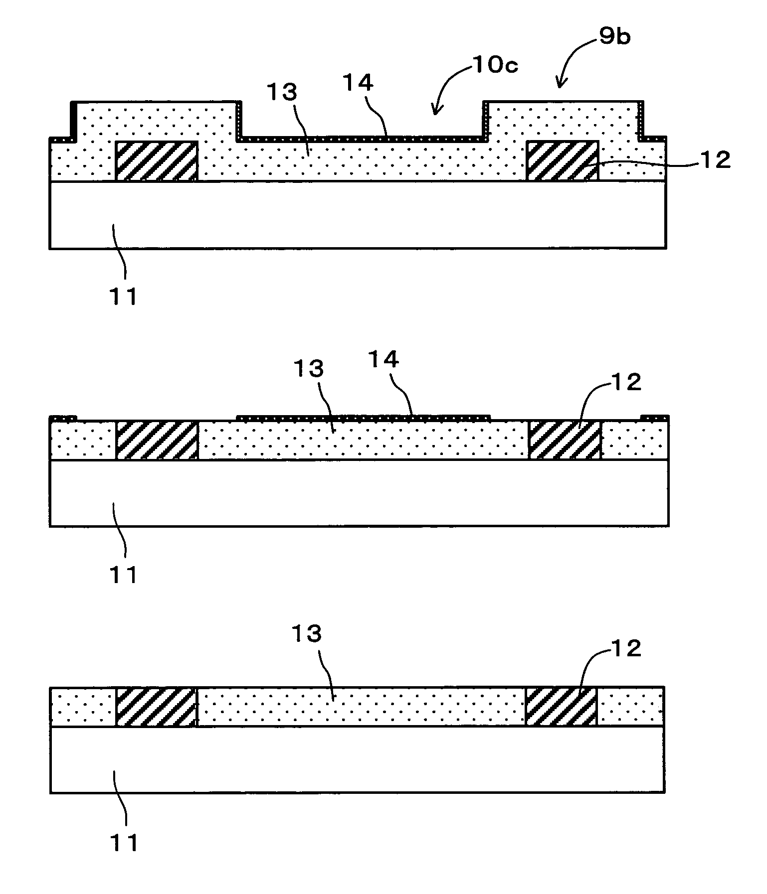
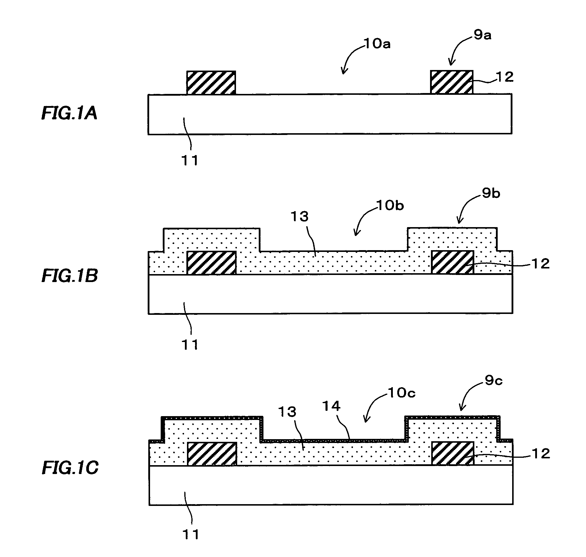
[0024]A semiconductor device fabrication method according to a first embodiment of the invention comprises the steps of: (1) exposing a silicon layer by removing a portion of an insulating layer above a projected part of the silicon layer, the insulating layer covering the silicon layer; and (2) chemically and mechanically polishing the exposed silicon layer with a polishing slurry for the silicon layer while protecting the silicon layer with the remaining of the insulating layer.
1-1. Step of Exposing a Silicon Layer by Removing a Portion of an Insulating Layer Above a Projected Part of the Silicon Layer, the Insulating Layer Covering the Silicon Layer
[0025]A silicon layer may be a polycrystalline silicon layer, an amorphous silicon layer or a single crystal silicon layer. Further, the term “silicon layer” includes a layer of silicon alloy such as silicon germanium.
[0026]A silicon oxide such as silicon dioxide or a silicon nitride can be used for the insulating la...
second embodiment
2. Second Embodiment
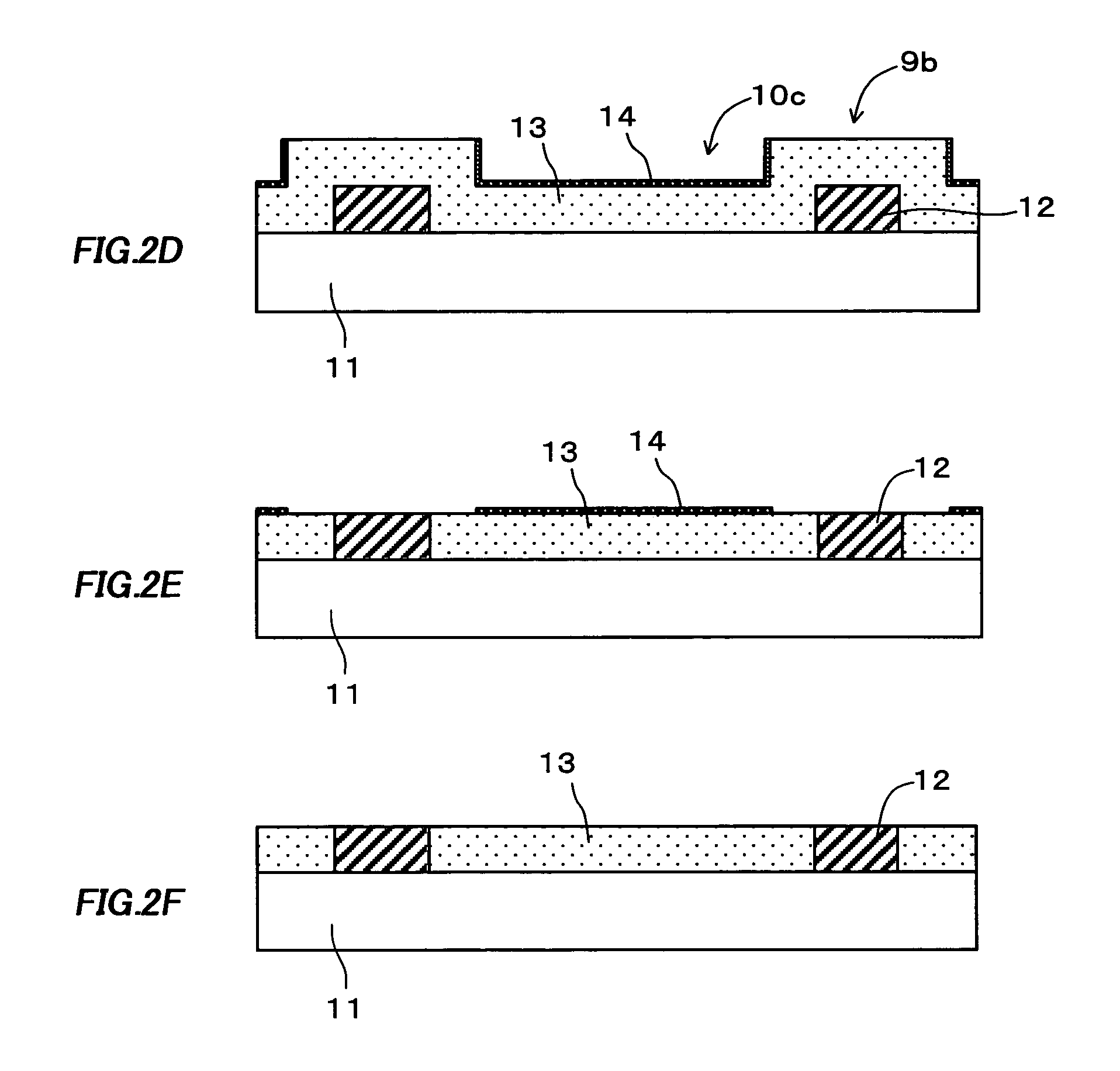
[0034]A semiconductor device fabrication method according to a second embodiment of the invention comprises the steps of: (1) forming a silicon layer having a thickness substantially the same as or thinner than the height of a projected part on a substrate so as to cover the surface of the substrate, the projected part being formed of a first insulating layer; (2) forming a second insulating layer covering the silicon layer; (3) exposing the silicon layer by removing a portion of the second insulating layer above the projected part on the substrate; (4) substantially leveling the silicon layer and exposing the first insulating layer by chemically and mechanically polishing the exposed silicon layer while protecting the silicon layer with the remaining of the second insulating layer and using the remaining of the second insulating layer or the projected part of the first insulating layer as a stopper layer; and (5) removing the remaining of the second insulating l...
third embodiment
3. Third Embodiment
[0049]A semiconductor device fabrication method according to a third embodiment of the invention comprises the steps of: (1) forming a silicon layer having a thickness thicker than the height of a projected part on a substrate so as to cover the surface of the substrate, the projected part being formed of a first insulating layer; (2) forming a second insulating layer covering the silicon layer; (3) exposing the silicon layer by removing a portion of the second insulating layer above the projected part on the substrate; (4) substantially leveling the silicon layer by chemically and mechanically polishing the exposed silicon layer while protecting the silicon layer with the remaining of the second insulating layer and using the remaining of the second insulating layer as a stopper layer; (5) removing the remaining of the second insulating layer; and (6) exposing the first insulating layer by chemically and mechanically polishing the substantially leveled silicon la...
PUM
| Property | Measurement | Unit |
|---|---|---|
| width | aaaaa | aaaaa |
| thickness | aaaaa | aaaaa |
| insulating | aaaaa | aaaaa |
Abstract
Description
Claims
Application Information
 - R&D
- Intellectual Property
- Life Sciences
- Materials
- Tech Scout
- Unparalleled Data Quality
- Higher Quality Content
- 60% Fewer Hallucinations
Browse by: Latest US Patents, China's latest patents, Technical Efficacy Thesaurus, Application Domain, Technology Topic, Popular Technical Reports.
© 2025 PatSnap. All rights reserved.Legal|Privacy policy|Modern Slavery Act Transparency Statement|Sitemap|About US| Contact US: help@patsnap.com


