Low power photomultiplier tube circuit and method therefor

Active Publication Date: 2006-04-18
SANDIA NAT LAB
View PDF14 Cites 37 Cited by
  • Summary
  • Abstract
  • Description
  • Claims
  • Application Information

AI Technical Summary

Benefits of technology

[0021]The disclosed apparatus and method provides for a PMT circuit characterize

Problems solved by technology

High gain and fast rise time, however, are purchased with high power consumption rendering many applications problematic where it would be useful to power the PMT u

Method used


Image

  • Low power photomultiplier tube circuit and method therefor
  • Low power photomultiplier tube circuit and method therefor
  • Low power photomultiplier tube circuit and method therefor

Examples


Embodiment Construction

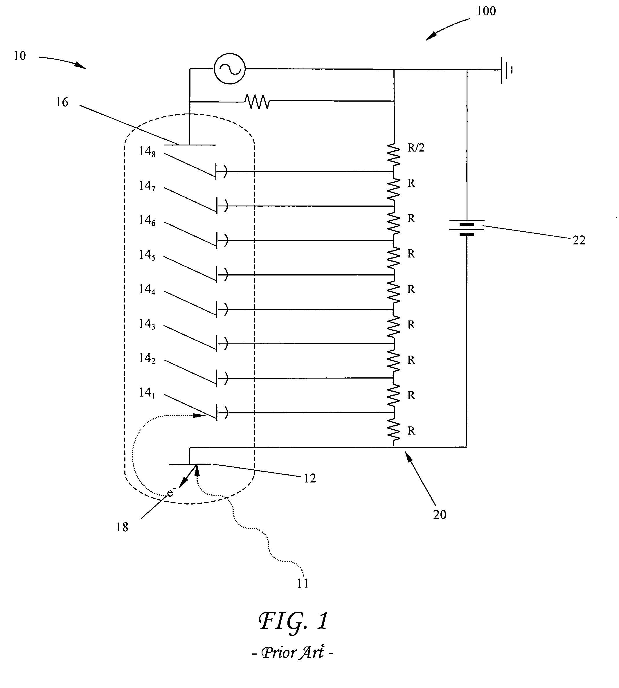
[0025]A conventional biasing circuit 100 for providing electrical energy to a PMT is shown in FIG. 1. The circuit includes a PMT 10 which itself includes a photocathode 12, one or more electron multiplying element (dynode) stages 14, and an anode 16, hereinafter collectively referred to as the PMT elements. PMTs are well known in the art and operate as follows. The photocathode has a photoemissive material (not shown) that ejects electrons in response to electromagnetic radiation 11, such as photons of light striking it. Ejected electrons 18 are then attracted toward a first dynode stage 14, by a voltage differential where (typically) several more electrons are ejected for every electron “falling” onto the dynode. This process of electron ejection and multiplication is generally repeated several more times through several additional dynode stages 142–148, successively biased with an increasingly lower negative voltage moving toward anode 16, which is held at ground. Ejected electron...


PUM


Abstract

An electrical circuit for a photomultiplier tube (PMT) is disclosed that reduces power consumption to a point where the PMT may be powered for extended periods with a battery. More specifically, the invention concerns a PMT circuit comprising a low leakage switch and a high voltage capacitor positioned between a resistive divider and each of the PMT dynodes, and a low power control scheme for recharging the capacitors.

Description

STATEMENT OF GOVERNMENT INTEREST[0001]This invention was made with Government support under government contract DE-AC04-94AL85000 awarded by the U.S. Department of Energy to Sandia Corporation. The Government has certain rights in the invention, including a paid-up license and the right, in limited circumstances, to require the owner of any patent issuing in this invention to license others on reasonable terms.BACKGROUND OF THE INVENTION[0002]1. Technical Field[0003]Disclosed is an electrical circuit for a photomultiplier tube (PMT) that reduces power consumption. More specifically, the invention concerns a PMT circuit comprising a low leakage switch and capacitor positioned between the resistive divider and each of the PMT electron multiplying elements (dynodes), a low power control scheme for recharging the capacitors, and a low power scheme for delivering high voltage to the PMT.[0004]2. Related Art[0005]Photomultiplier tubes are well known in the art having been developed well o...

Claims


Application Information

Patent Timeline
IPC IPC(8): H01J40/14
CPCH01J43/28
Inventor BOCHENSKI, EDWIN B.SKINNER, JACK L.DENTINGER, PAUL M.LINDBLOM, SCOTT C.
Owner SANDIA NAT LAB
Why Eureka
Try Eureka