Magnetic resonance imaging apparatus and method incorporating multi-mode gradient coil unit

a gradient coil unit and magnetic resonance imaging technology, applied in the field of magnetic resonance imaging apparatus and method incorporating a multi-mode gradient coil unit, can solve the problems of reducing the available access space and difficult to properly access the patient, and achieve the effects of reducing the winding density, and increasing the winding density

Active Publication Date: 2006-04-18
TOSHIBA MEDICAL SYST CORP
View PDF6 Cites 6 Cited by
  • Summary
  • Abstract
  • Description
  • Claims
  • Application Information

AI Technical Summary

Benefits of technology

[0011]The exemplary magnetic resonance imaging apparatus also may simply be a gradient coil unit including a plurality of gradient coils; wherein each gradient coil comprises: a first gradient coil part; and a second gradient coil part having at least one of the characteristics of (a) intensity of gradient magnetic field, (b) slew rate, (c) linearity and (d) changing rate of the magnetic field that is different from the corresponding characteristics of the first gradient coil part part.
[0012]The exemplary magnetic resonance imaging apparatus having gradient coils and shield coils as well as an RF coil and an operation control unit may have each gradient coil including a plurality of gradient coil parts that are located on a respectively corresponding single layer and each shield coil corresponds to a respective gradient coil part and is located on a different layer.
[0013]The exemplary magnetic resonance imaging apparatus having a plurality of gradient coils and a plurality of shield coils as well as an RF coil and an operation control unit may have each gradient coil including a plurality of gradient coil parts that are located on a respectiv

Problems solved by technology

However, such a structure where two kinds of coils are put on two different layers can make the diameter of a patient access opening whe

Method used


Image

  • Magnetic resonance imaging apparatus and method incorporating multi-mode gradient coil unit
  • Magnetic resonance imaging apparatus and method incorporating multi-mode gradient coil unit
  • Magnetic resonance imaging apparatus and method incorporating multi-mode gradient coil unit

Examples


Embodiment Construction

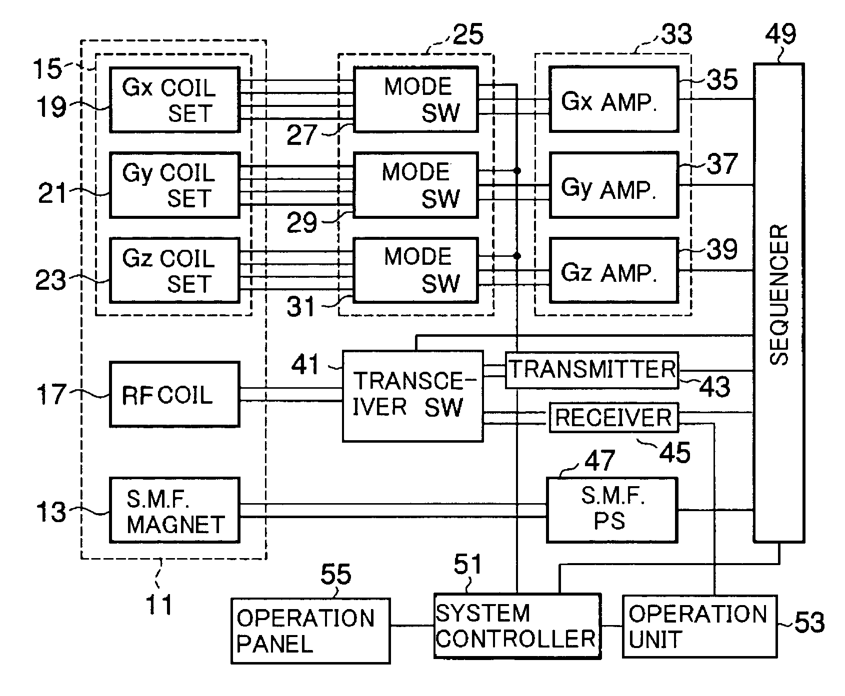
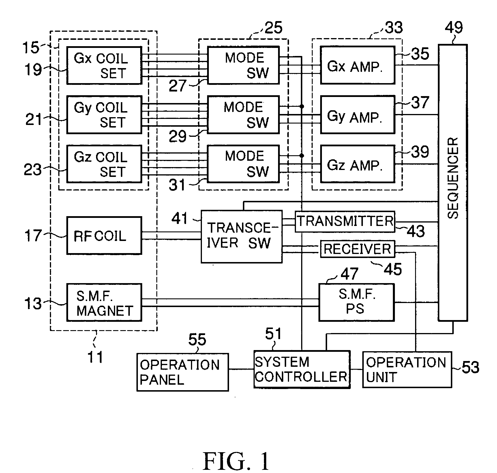
[0053]With reference to drawings, a first embodiment of a gradient coil unit and a magnetic resonance imaging apparatus are explained. FIG. 1 shows a block diagram of the magnetic resonance imaging apparatus that has a gradient coil unit according to the first embodiment. A magnet unit 11 has an approximately cylindrically shaped imaging space (opening). At the time of imaging, a patient laid on a bed plate is inserted into the imaging space. Rectilinear orthogonal three dimensional axes (XYZ) are defined as below for explanation. The Z-axis corresponds to a center axis of the opening. The magnet unit 11 includes a static magnet 13, a gradient magnetic field coil unit 15 and an RF coil 17. The gradient coil unit 15 is located inside the static magnetic field magnet 13. The RF coil 17 is located inside the gradient coil unit 15. A static magnetic field power supply 47 supplies current to the static magnetic field magnet 13. Thereby, the imaging space is filled with static magnetic fi...


PUM


Abstract

A gradient coil or shield coil includes a first gradient coil part and a second gradient coil part having at least one different characteristic of (a) intensity of gradient magnetic field, (b) slew rate, (c) linearity and/or (d) changing rate of the magnetic field (as compared to characteristics of the first gradient coil part. In another aspect, a gradient coil includes a first portion close to a center of the gradient coil, a second portion which is outside of the first portion and which has a lower winding density than the first portion and a third portion which is outside of the second portion and which has a higher winding density than the second portion.

Description

CROSS-REFERENCE TO RELATED APPLICATIONS[0001]This application is based upon and claims the benefit of priority from prior Japanese Patent Application No. 2002-381384 filed on Dec. 27, 2002, and Japanese Patent Application No. 2003-205734 filed on Aug. 4, 2003, the entire contents of which are both hereby incorporated herein by reference.FIELD OF THE INVENTION[0002]The present invention relates generally to magnetic resonance imaging apparatus and method incorporating a multi-mode gradient coil unit.BACKGROUND OF THE INVENTION[0003]In magnetic resonance phenomenon, a group of nuclei with a magnetic moment are placed in a homogeneous static magnetic field. The nuclei absorb energy from a high frequency (RF) magnetic field rotating at a specific (Larmor) frequency, and emit the absorbed energy as an NMR response after the high frequency (RF) magnetic field is removed. In order to create an image of chemical or physical information in a living body using such a phenomenon, it is necessa...

Claims


Application Information

Patent Timeline
IPC IPC(8): G01V3/00G01R33/385
CPCG01R33/385
Inventor SAKAKURA, YOSHITOMO
Owner TOSHIBA MEDICAL SYST CORP
Why Eureka
Try Eureka