Al technical title is built by PatSnap Al team. It summarizes the technical point description of the patent document.
a detector and position technology, applied in the field of position detectors, can solve the problems of system failure to operate in pulse-echo mode of operation, inability to detect positional errors, and inability to operate in pulse-echo mode, etc., and achieve the effect of convenient and suitability
Inactive Publication Date: 2006-04-18
SINNAPTIX
View PDF132 Cites 153 Cited by
Summary
Abstract
Description
Claims
Application Information
AI Technical Summary
This helps you quickly interpret patents by identifying the three key elements:
Problems solved by technology
Method used
Benefits of technology
[0013]The different spatial frequency variations of the output signals are preferably achieved by shaping the conductors in a predetermined manner over the measurement path. In particular, the two conductors preferably extend in a geometrically varying manner having different characteristic dimensions along the measurement path. This can be achieved, for example, by using windings having a different pitch along the measurement path. By using such windings, a position measurement can be obtained across the entire measurement path and an indication of the relative tilt of the two members in the measurement direction can be obtained. This system therefore avoids the need for having a large number of overlapping windings which are spread out over the measurement path and therefore does not suffer from the problems discussed above.
[0014]By providing a similar position detector for detecting the re...
Problems solved by technology
However, the use of the conductive screen in place of the resonator has the disadvantages that the output signal levels are much smaller and that the system cannot be operated in a pulse-echo mode of operation, in which a short burst of excitation current is applied to the excitation winding and then, after the excitation current has ended, detecting and processing the signals induced in the sensor coils.
A problem common to all of these known position sensors is that a positional error is introduced into the measurements if the move...
Method used
Image
Click on the blue label to locate the original text in one second.
Reading with bidirectional positioning of images and text.
Examples
Embodiment Construction
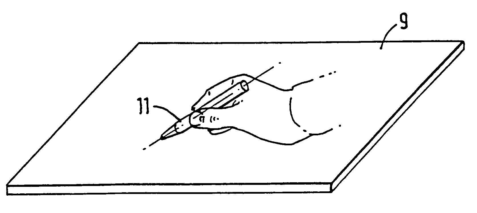
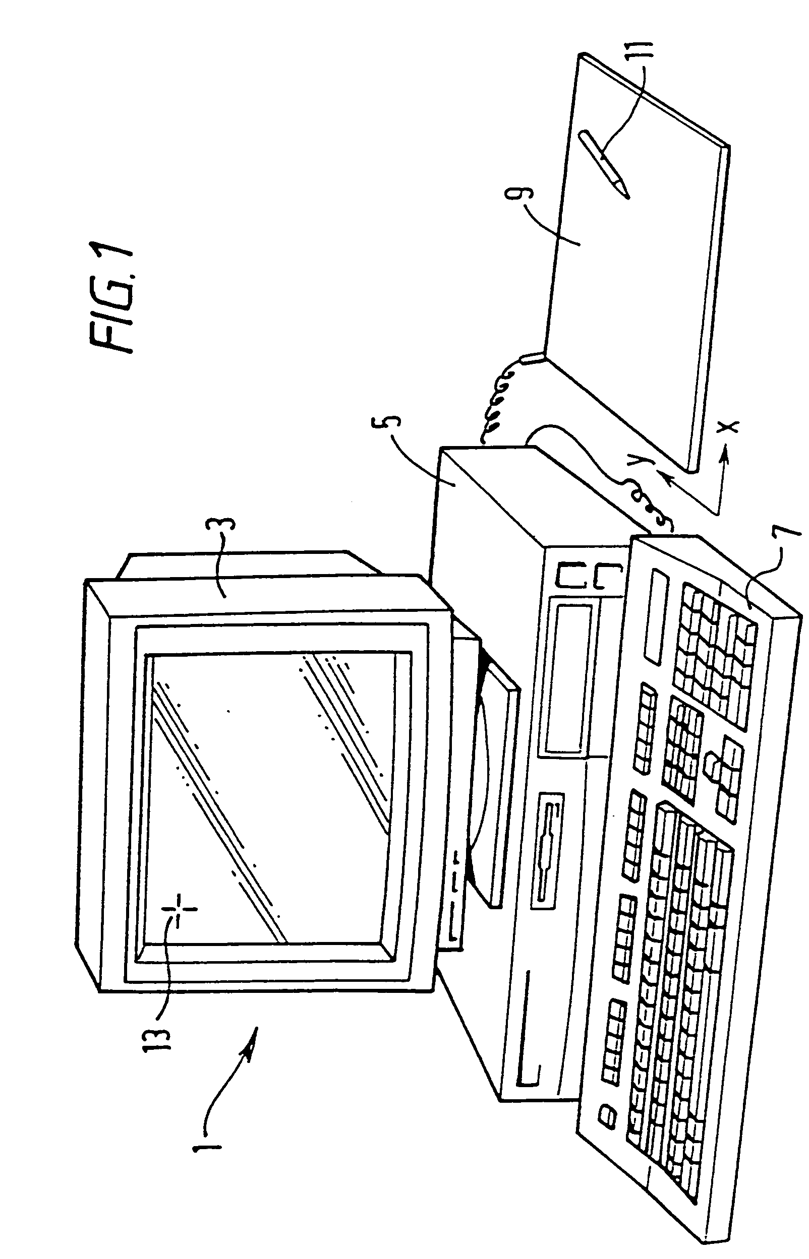
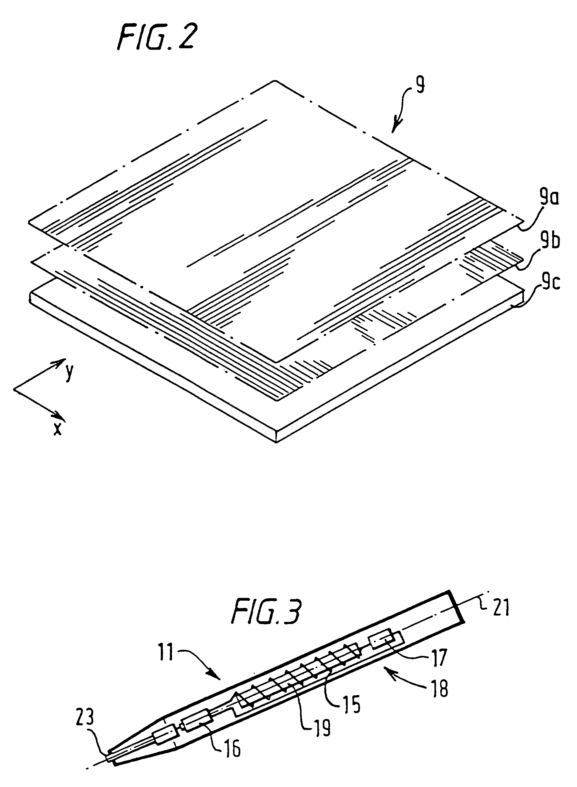
[0059]FIG. 1 schematically shows a computer system 1 having a display 3, a main processing unit 5, a keyboard 7, an X-Y digitising tablet 9 and a stylus 11. The X-Y digitising system senses the current X-Y position of the stylus 11 over the tablet 9 and uses the sensed position to control the location of a cursor 13 on the display 3. FIG. 2 schematically shows an exploded view of the digitising tablet 9. As shown, the digitising tablet comprises a first group of windings 9-a, a second group of windings 9-b and a base portion 9-c for supporting the two groups of windings 9-a and 9-b. The group of windings 9-a is used for determining the X coordinate position of the stylus 11 and the group of windings 9-b are used for determining the Y coordinate position of the stylus 11.
[0060]FIG. 3 shows in more detail the form of the stylus 11 shown in FIG. 1. As shown, the stylus 11 comprises a coil 15 which is connected in series, via a switch 16, to a capacitor 17 to form a resonant circuit, ge...
PUM
Abstract
A position detector is provided for detecting the relative movement of first and second members which are mounted for relative movement along a measuring path. One of the members comprises a magnetic field generator for generating a magnetic field and the other member comprises first and second conductors which are inductively coupled to said magnetic field generator. The arrangement of the first and second conductors and the magnetic field generator is such that output signals are generated in a first and second receive circuits whose position varies with the relative movement between the two members. In addition to carrying information relating to the relative position between the two members, the signals induced in the receive circuits also comprise information defining the relative orientation of the two movable members, and by suitable processing of the received signals the relative orientation of the two members can also be determined. In a preferred form of the invention, the system operates to define the relative position and orientation of the two movable members in first and second directions from which the relative orientation of the two members in a plane containing the two directions can be determined. The signals induced in the receive circuits can also be processed to give an indication of the gap between the two circuits and to provide an indication of the full relative orientation of the two members.
Description
RELATED APPLICATIONS[0001]This is a division of application Ser. No. 10 / 278,984 filed Oct. 24, 2002 which is a division of application Ser. No. 09 / 627,423 filed Jul. 27, 2000 now U.S. Pat. No. 6,489,899 (now allowed) which is, in turn, a continuation of application Ser. No. 09 / 111,885 filed Jul. 8, 1998 (now U.S. Pat. No. 6,249,234). Although no domestic priority is claimed prior to Jul. 8, 1998, it is noted that application Ser. No. 09 / 111,885 was, in turn, a continuation-in-part of application Ser. No. 08 / 737,505 filed Dec. 12, 1996 (now U.S. Pat. No. 5,815,091 issued Sep. 29, 1998), the contents of which are incorporated by reference. This application is also related to copending divisional application Ser. No. 10 / 108,266 filed Mar. 28, 2002.BACKGROUND OF THE INVENTION[0002]1. Field of the Invention[0003]2. Related Art[0004]The present invention relates to position sensors generally. The invention has particular although not exclusive relevance to non-contact linear and rotary po...
Claims
Application Information
Patent Timeline
Application Date:The date an application was filed.
Publication Date:The date a patent or application was officially published.
First Publication Date:The earliest publication date of a patent with the same application number.
Issue Date:Publication date of the patent grant document.
PCT Entry Date:The Entry date of PCT National Phase.
Estimated Expiry Date:The statutory expiry date of a patent right according to the Patent Law, and it is the longest term of protection that the patent right can achieve without the termination of the patent right due to other reasons(Term extension factor has been taken into account ).
Invalid Date:Actual expiry date is based on effective date or publication date of legal transaction data of invalid patent.