Characterizing aberrations in an imaging lens and applications to visual testing and integrated circuit mask analysis

a technology of aberration and imaging lens, applied in the field of imaging lens system, can solve the problems residual aberrations still contributing significant spillover, and affecting the projection printing of mask patterns in integrated circuit layout, so as to achieve the effect of reducing the effect of human perception

Inactive Publication Date: 2006-04-18
RGT UNIV OF CALIFORNIA
View PDF3 Cites 85 Cited by
  • Summary
  • Abstract
  • Description
  • Claims
  • Application Information

AI Technical Summary

Benefits of technology

[0007]Another aspect of the invention lies in a pattern-matching method for predicting worst case locations of residual aberration induced feature changes in projection printing large layouts including chip layouts used in integrated circuit manufacturing. A CAD system can rapidly determine locations in large layouts that are most impacted by aberrations in projection printing. For this application, aberrations are accurately modeled as producing spillover between mask openings with a localized pattern that is the inverse Fourier transform (IFT) of the optical path difference (OPD) function in the pupil. The novel function in the CAD system then quickly rank orders all pattern edges and corners according to the degree of similarity of their surrounding layout to the IFT function.

Problems solved by technology

At these dimensions, the projection printing of mask patterns in integrated circuit layout can be adversely impacted by small residual aberrations in the lens system.
While the quality metric (Strehl ratio) of today's projection printers is within a few percent of unity, residual aberrations still contribute significant spillover of signals from one mask opening in another.
These spillover effects degrade the image quality with position within the field of the die.

Method used


Image

  • Characterizing aberrations in an imaging lens and applications to visual testing and integrated circuit mask analysis
  • Characterizing aberrations in an imaging lens and applications to visual testing and integrated circuit mask analysis
  • Characterizing aberrations in an imaging lens and applications to visual testing and integrated circuit mask analysis

Examples


Embodiment Construction

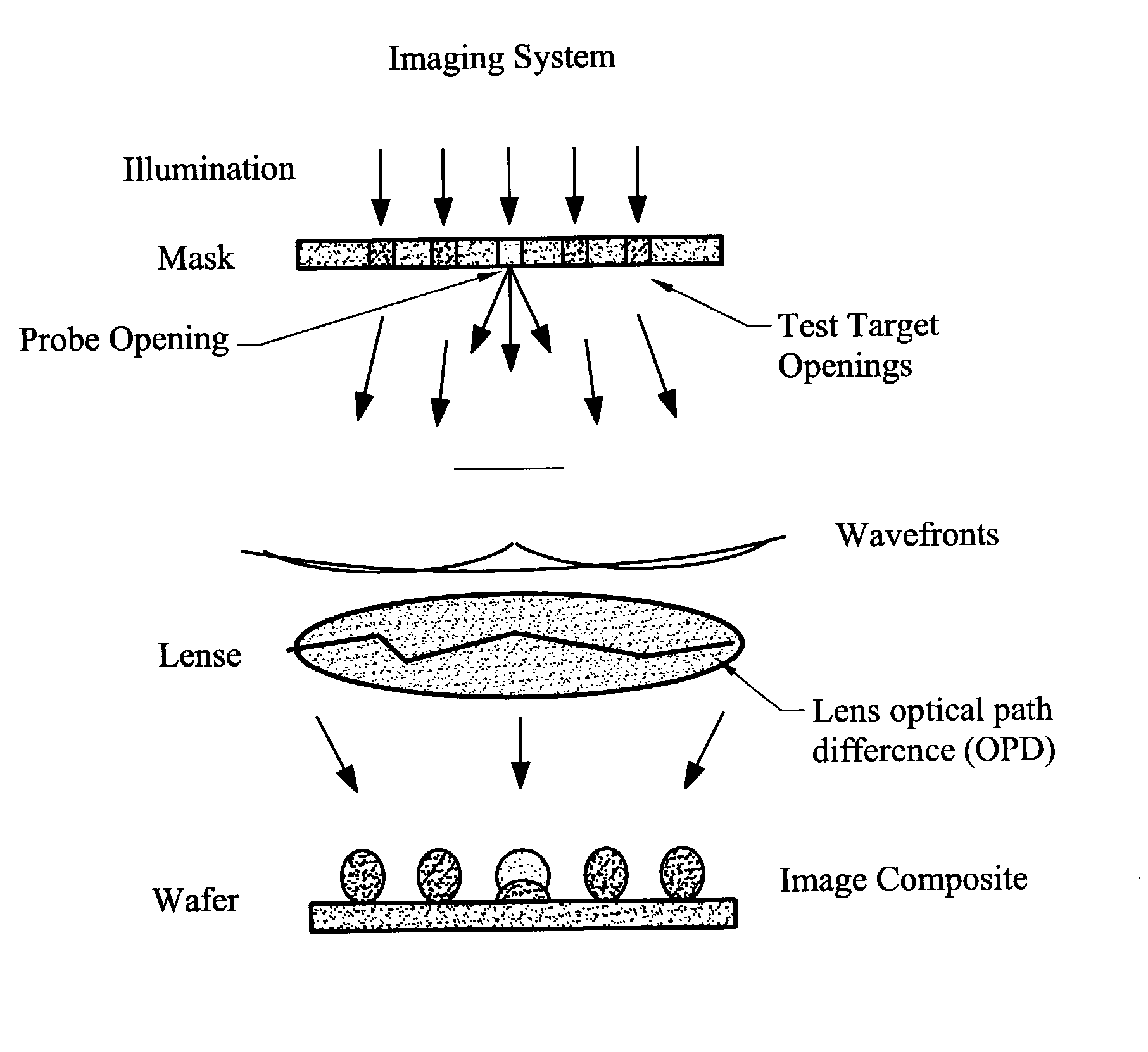
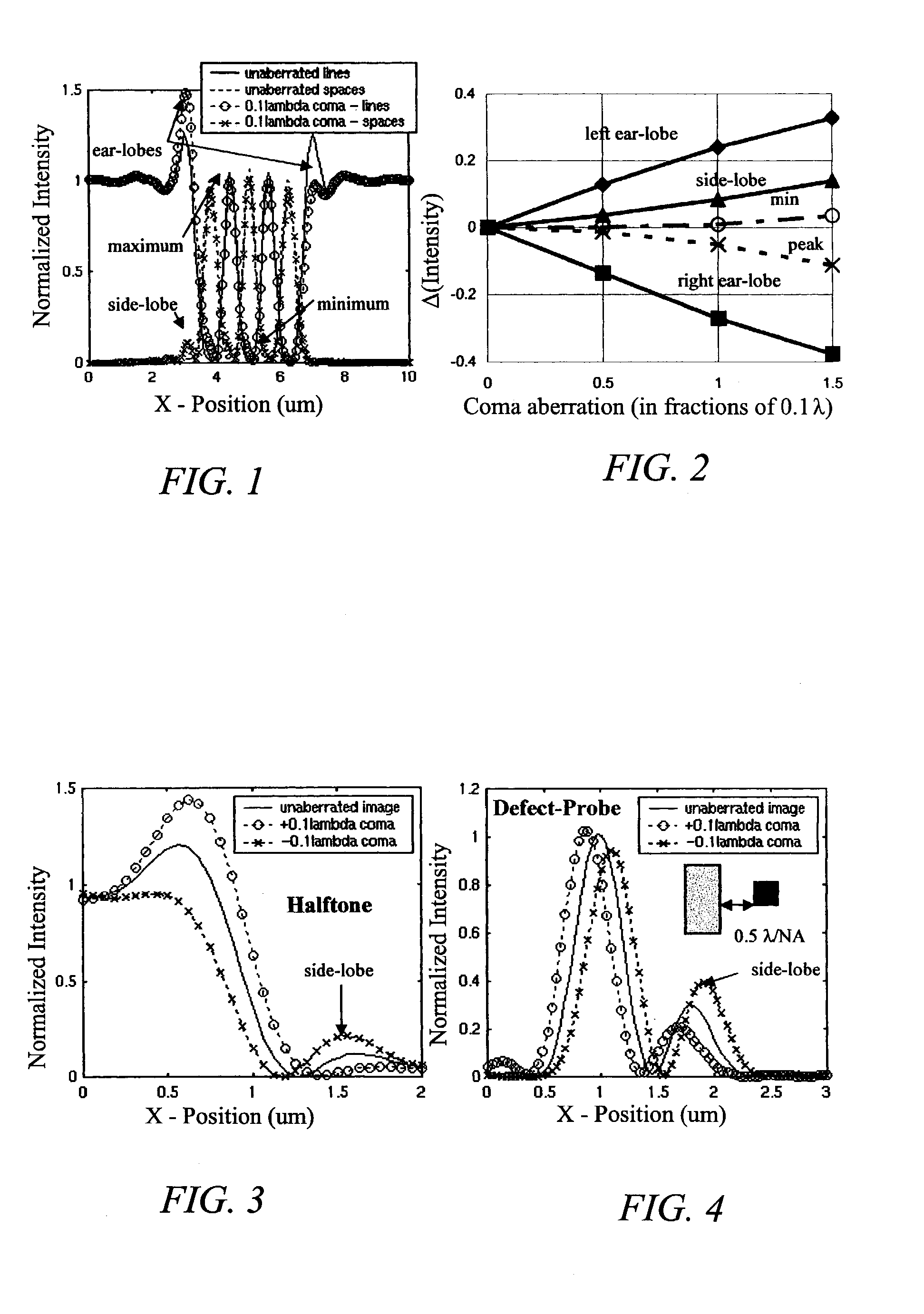
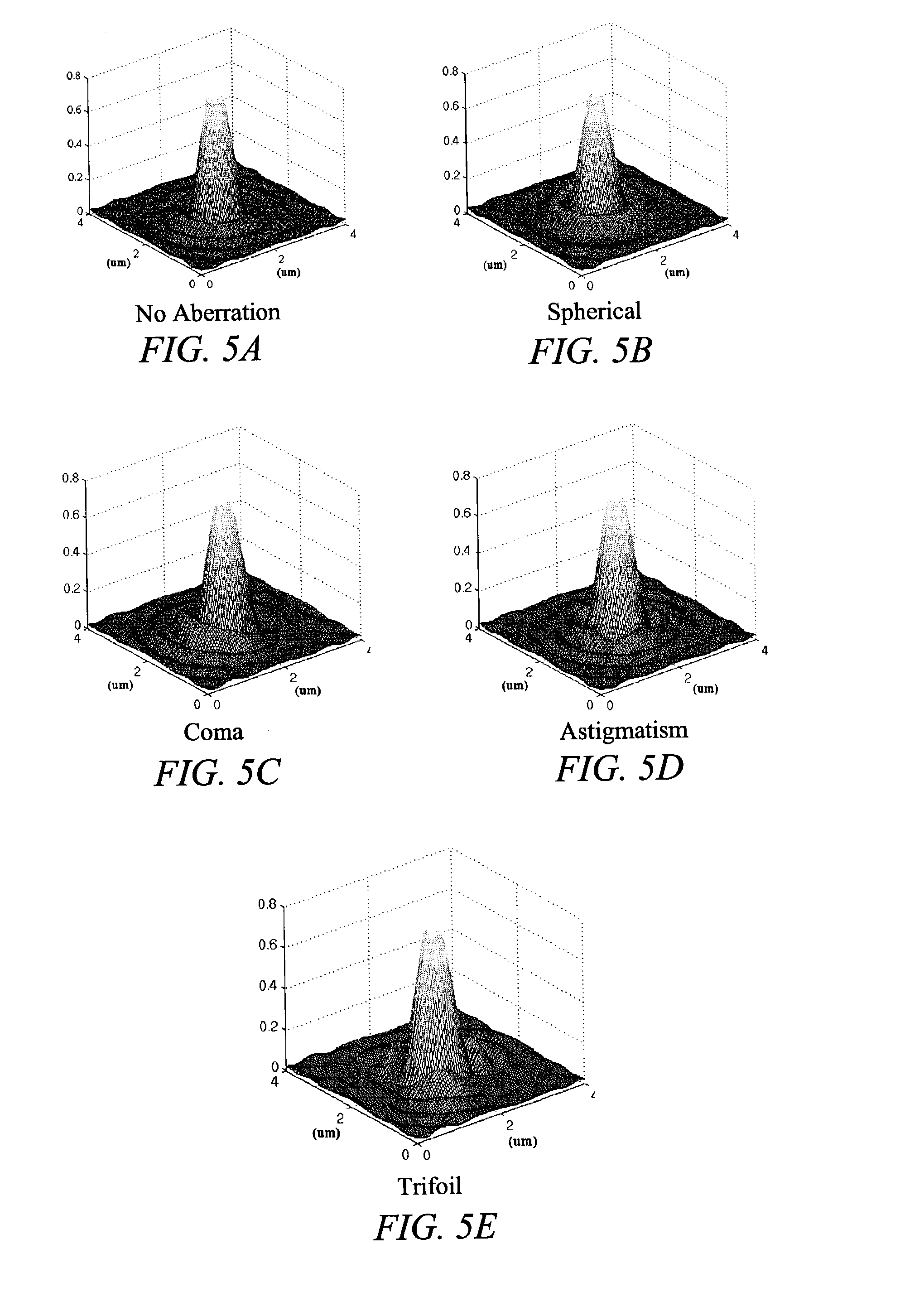
[0064]The impact of aberrations on lithography is an increasing concern in extending the limits of optical lithography. Brunner has given an excellent overview of the subject (T. A. Brunner, “Impact of lens aberrations on optical lithography, IBM J. Res. Develop, Vol. 41, No. 1 / 2, pp. 57–67, March 1997) and the large number of photoresist-based techniques were recently classified by Kirk (J. Kirk, “Review of photoresist based lens evaluation methods,” SPE 4000, 2000). Other relevant work includes focus monitors based on shifts of phase-edge line positions with focus (T. A. Brunner, A. L. Martin, R. M. Marino, C. P. Ausschnitt, T. H. Newman and M. S. Hibbs, “Quantitative stepper metrology using the focus monitor test mask,” SPIE Vol. 2197, pp. 541–549, 1994), measurements of localized pupil tilt based translation of large features projected from a special aperture restricting mask by Litel, SEM's of shapes of images of λ / 2 phase-dots by Dirksen et al., and measurements of exposure se...


PUM

PropertyMeasurementUnit
sizeaaaaaaaaaa
wavelengthaaaaaaaaaa
widthaaaaaaaaaa

Abstract

Aberrations in a lens and lens system are identified by projecting an optical beam through a mask having an opening (probe) and a surrounding open geometry (pattern) and through the lens to an image plane. Lens aberrations are identified from the combined intensity of the beam in the image plane. In one embodiment the pattern is a plurality of rings concentric with the probe. Spillover between the probe and the geometry becomes intermixed in passing through the lens and alters the light intensity in the image plane. Vision of a patient can be tested by providing a plurality of probe openings and surrounding geometries that are illuminated. The patient then compares the images for brighter and darker probes as a measure of pupil aberrations. Areas in an integrated circuit mask layout impacted by aberrations in projection printing can be identified by sequentially comparing an aberration function to a mask layout, which can then be used to modify the mask layout.

Description

CROSS-REFERENCES TO RELATED APPLICATIONS[0001]This application claims priority from provisional application Ser. No. 60 / 322,381, filed Sep. 11, 2001, which is incorporated herein for all purposes.STATEMENT AS TO RIGHTS TO INVENTIONS MADE UNDER FEDERALLY SPONSORED RESEARCH OR DEVELOPMENT[0002]The U.S. Government has rights in the disclosed invention pursuant to DARPA Contract MDA 972-97-1-0010 and DARPA Grant MDA 972-01-1-0021 with the University of California at Berkeley.BACKGROUND OF THE INVENTION[0003]This invention relates generally to imaging lens systems, and more particularly the invention relates to the characterization of aberrations in an optical lens and lens system and to visual testing and integrated circuit mask analysis.[0004]In the fabrication of electronic integrated circuits, line patterns of less than a tenth of a micron are now being developed. This is less than 1 / 500 the width of a human hair. At these dimensions, the projection printing of mask patterns in integ...

Claims


Application Information

Patent Timeline
Patent Type & Authority Patents(United States)
IPC IPC(8): G01B11/02G01B9/02A61B3/032G03F7/20
CPCG01M11/0264G03F7/706
Inventor NEUREUTHER, ANDREW R.ADAM, KOSTASROBINS, GARTH C.GENNARI, FRANK E.
Owner RGT UNIV OF CALIFORNIA
Why Eureka
Try Eureka