Hybrid broadband light source

a broadband light source and hybrid technology, applied in the field of optical communication devices, can solve the problems of low output power insufficient use of white light sources and eeleds, and complex construction, and achieve the effect of high output power, economical and effectiv

Inactive Publication Date: 2006-04-18
SAMSUNG ELECTRONICS CO LTD
View PDF2 Cites 5 Cited by
  • Summary
  • Abstract
  • Description
  • Claims
  • Application Information

AI Technical Summary

Benefits of technology

[0018]Accordingly, the present invention has been made to reduce or overcome the above-mentioned problems occurring in the prior art. One object of the present invention is to provide a broadband light source which can obtain high output power in a selective wavelength band in an economical and effective manner.

Problems solved by technology

However, white light sources and EELEDs have low output power and are not suitable as a light source for a WDM-PON and SDLs as they output relatively high power.
Thus, white light sources and EELEDs are insufficient for use as broadband light sources for a WDM-PON as compared to EDFAs.
Disadvantageously, however, their construction becomes complicated in order to meet with the above requirements, and thus are not economical in price.
However, such a broadband optical source has a number of limitations, including employing expensive components for generating ASE serving as a seed, thus it is not economical.
In addition, the ASE is not effective because the portion of the spectrum beyond a predetermined wavelength band is removed in the band-pass filter 160.

Method used


Image

  • Hybrid broadband light source
  • Hybrid broadband light source
  • Hybrid broadband light source

Examples


first embodiment

[0027]FIG. 3 is a diagram of a hybrid broadband light source according to the present invention. The broadband light source 300 comprises an ASE light source module 320, first and second isolators 330, 335, a gain medium 340, a pump light source 350, and a wavelength selective coupler 360. The ASE light source module 320, the first isolator 330, the gain medium 340, the wavelength selective coupler 360, and the second isolator 335 are connected in series using a first optical waveguide 310. The pump light source 350 is connected in parallel to the gain medium 340 using a second optical waveguide 315.

[0028]The ASE light source module 320 is installed at a terminal end of the broadband light source 300. The ASE light source module 320 generates and outputs ASE. The ASE light source module 320 is a semiconductor ASE light source of a single module and may incorporate an ASE light source fabricated from a low-price semiconductor including a low-price EELED or SLD having the desired wave...

second embodiment

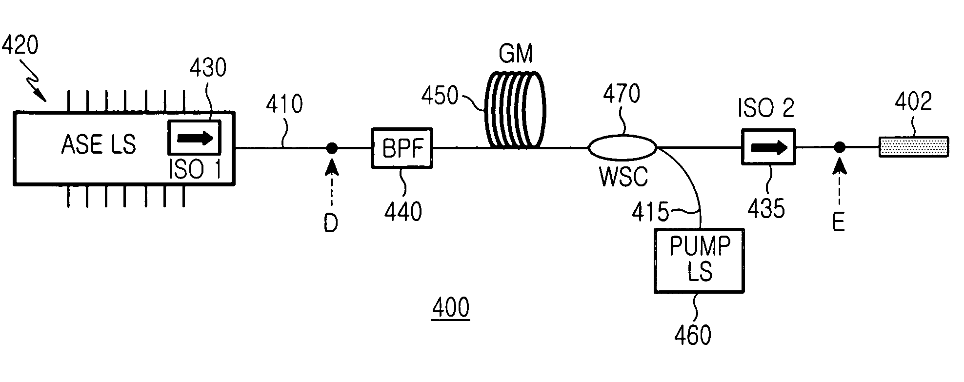
[0034]FIG. 4 is a diagram of a hybrid broadband light source according to the present invention. The broadband light source 400 comprises an ASE light source module 420, a band-pass filter 440, a gain medium 450, a pump light source 460, a wavelength selective coupler 470, and a second isolator 435. The ASE light source module 420, the band-pass filter 440, the gain medium 450, the wavelength selective coupler 470, and the second isolator 435 are connected in series using a first optical waveguide 410. The pump light source 460 is connected in parallel to the gain medium 450 using a second optical waveguide 415.

[0035]The ASE light source module 420 is installed at a terminal end of the broadband light source 300. The ASE light source module 420 generates and outputs ASE. At an output end of the ASE light source module 420, a first isolator 430 is directly integrated, and the first isolator 430 passes the ASE inputted to the first isolator and blocks light the opposite direction.

[003...


PUM


Abstract

Disclosed is a hybrid broadband optical source comprising an amplified spontaneous emission (ASE) light source module to generate ASE, a gain medium to amplify the ASE, a pump light source to generate pump light, and a wavelength selective coupler to supply the pump light to the gain medium.

Description

CLAIM OF PRIORITY[0001]This application claims priority to an application entitled “Hybrid Broadband Light Source,” filed with the Korean Intellectual Property Office on Dec. 19, 2003 and assigned Serial No. 2003-93857, the contents of which are hereby incorporated by reference.BACKGROUND OF THE INVENTION[0002]1. Field of the Invention[0003]The present invention relates to an optical communication device, in particular to a broadband light source.[0004]2. Description of the Related Art[0005]In constructing wavelength division multiplexing passive optical networks (WDM-PON), which are technology candidates for high-speed fiber-to-the-home (FTTH) applications, a low-price broadband light source are required. Together with a wavelength locked (Fabry Perot laser diode (FP-LD), such a broadband light source plays an important role in concurrently accommodating a plurality of subscribers. In addition, when such a broadband light source is employed in an optical communication system incorp...

Claims


Application Information

Patent Timeline
Patent Type & Authority Patents(United States)
IPC IPC(8): H01S3/00G02B6/26H01J13/28H01S3/067H01S3/16
CPCH01S3/06754H01S3/1616H01S3/1613H01S3/06795H01S3/0064H01S3/094023H01S2301/02
Inventor KIM, SANG-HOHWANG, SEONG-TAEKSHIM, CHANG-SUPOH, YUN-JE
Owner SAMSUNG ELECTRONICS CO LTD
Why Eureka
Try Eureka