Dichroic polarizer and material

a dichroic polarizer and dichroic polarizer technology, applied in the field of thermoresistant and light-resistant dichroic polarizers, can solve the problems of low angular characteristics, limited applicability, and high light transmittance of oriented polarizers,

Inactive Publication Date: 2006-04-18
NITTO DENKO CORP
View PDF20 Cites 13 Cited by
  • Summary
  • Abstract
  • Description
  • Claims
  • Application Information

AI Technical Summary

Benefits of technology

[0008]The present invention provides an improved dichroic polarizer and material for its manufacture. More specifically, the invention provides dichroic polarizers which are based on thin films of dichroic organic materials, in particular organic dyestuffs applied onto the surface of a substrate, and the dichroic molecules are ordered into a crystalline structure.

Problems solved by technology

Despite the high polarizing efficiency of polarizers obtained from currently commonly used materials, they have a substantial disadvantage in that two cross-oriented polarizers have a high transmittance of light incident at an azimuth angle, especially at azimuth of ±45° relative to the axis of polarization.
Polarizers based on this material have a number of disadvantages, which limit its applicability.
In particular, it has insufficient polarizing efficiency and low angular characteristics.
This results in the fact that when used in various devices, which use two parallel polarizers of herein described type, there is some undesirable transmittance of unpolarized light incident at an angle to their surface.
One of the reasons of the above disadvantages is the fact that there is no control over the degree of absorption along the normal to the plane of the polarizer.

Method used


Image

  • Dichroic polarizer and material
  • Dichroic polarizer and material
  • Dichroic polarizer and material

Examples


Embodiment Construction

[0019]The present invention is now described in detail and with reference to the figures.

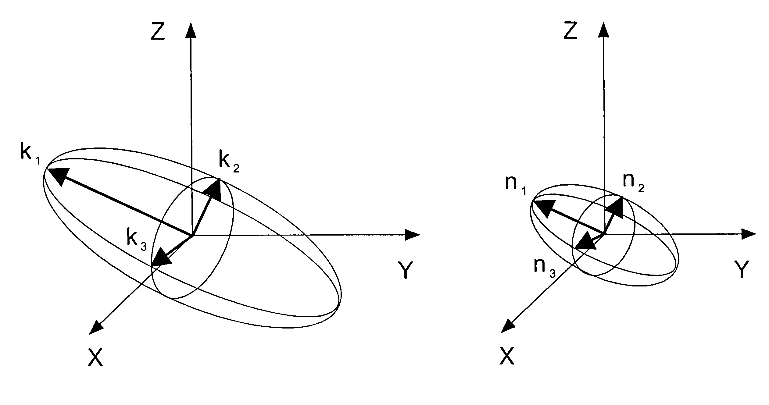
[0020]Optical properties of polarizers are characterized by the complex anisotropic refractive index Ni,j=√{square root over (εi,j·μii,j)}, where ei,j and μi,j are tensors of dielectric and magnetic transmittance. In the system of coordinates, in which the tensor of the dielectric transmittance is diagonal, Nm=nm−i·km, where nm is the refractive index, which characterizes the speed of light in the matter and the plane of polarization of which is parallel to the axis m, km is an imaginary part, which characterizes absorption of light with the plane of polarization along axis m and related to the absorption coefficient as follows:

Km=2π·km / λ,

where λ is the light wavelength. Angular dependence of the real and imaginary parts of the refractive index may be described with ellipsoids.

[0021]Iodine polarizers are characterized by the axial symmetry of components of Nm. Here major axis of the ellipsoid co...


PUM

PropertyMeasurementUnit
azimuth angleaaaaaaaaaa
distanceaaaaaaaaaa
speedaaaaaaaaaa

Abstract

The invention pertains to thermo-resistant and light-resistant dichroic polarizers based on thin films of dichroic matters, in particular organic dyestuffs, in which molecules are ordered in a crystalline structure and applied on the surface of the substrate. The dichroic polarizer is characterized by the fact that it contains at least one anisotropically absorbing film comprised of oriented molecules. Anisotropically absorbing film is characterized by the fact that for the major axes of the ellipsoids of the real and imaginary parts of anisotropic refraction coefficient in the range of at least one absorption band of the following is true on the area with linear dimensions no less than the maximum wavelength:
K1≧K2>K3(n1+n2)2>n3
where K1, K2, K3 and n1, n2, n3, are main values of the semiaxes of the ellipsoid representing the imaginary and real parts, accordingly, of the anisotropic refraction coefficient, and/or the anisotropically absorbing film is characterized by the fact that light transmission by two films with cross-oriented polarization axes does not increase at least in some range of wavelengths upon the deviation of its propagation from the normal to the polarizer plane.

Description

FIELD OF THE INVENTION[0001]The invention pertains to thermo-resistant and light-resistant dichroic polarizers, which are based on thin films of dichroic organic matters, in particular organic dyestuffs applied onto the surface of the substrate, dichroic molecules of which are ordered into a crystalline structure. The polarizers of the present invention can be used in applications with severe operating conditions. A wide application area includes but is not limited to for example, liquid crystal displays.BACKGROUND OF THE INVENTION[0002]Optical polarizing films have found wide use in a variety of industries. Many polarizers have been investigated and there are polarizers based on polymers, for example polyvinyl alcohol, which are made optically anisotropic by uniaxial stretching of a thin film of such polymer. The onset of optical anisotropy is due to stretching of the polymer molecules and their subsequent orientation along the direction of stretching as described in U.S. Pat. No. ...

Claims


Application Information

Patent Timeline
Patent Type & Authority Patents(United States)
IPC IPC(8): G02B5/30G02B27/28G02B1/08G02F1/1335
CPCG02B5/3033Y10T428/31515
Inventor BOBROV, YURI A.IGNATOV, LEONID Y.LAZAREV, PAVEL I.SAKHAROVA, ALLA Y.
Owner NITTO DENKO CORP
Why Eureka
Try Eureka