High-frequency superposing module for driving laser diode

a laser diode and superposition module technology, applied in semiconductor lasers, instruments, record information storage, etc., to achieve the effect of facilitating the adjustment of oscillating circuits and/or impedance matching circuits

Active Publication Date: 2006-04-18
MURATA MFG CO LTD
View PDF5 Cites 7 Cited by
  • Summary
  • Abstract
  • Description
  • Claims
  • Application Information

AI Technical Summary

Benefits of technology

[0011]According to a preferred embodiment of the present invention, a high-frequency superposing module drives a laser diode by supplying the laser diode with a drive current composed of a DC current and a high-frequency current superposed on the DC current. The high-frequency superposing module includes an oscillating circuit and an impedance matching circuit. The oscillating circuit includes an oscillating active element and a high-frequency blocking inductor. The impedance matching circuit includes a capacitor connected in series between the output terminal of the oscillating active element and a terminal through which a signal for driving the laser diode is output; and another capacitor connected in parallel between the drive-signal output terminal and the ground. The high-frequency blocking inductor is connected between the drive-signal output terminal and the source terminal of the oscillating active element, thus allowing the drive-signal output terminal to function as a power input terminal for the oscillating circuit.
[0012]With this unique structure, the oscillating circuit requires only one power supply and fewer terminals, thus contributing to the very compact design of the high-frequency superposing module. Thus, a user can easily implement the compact module in a circuit. Furthermore, the impedance matching circuit disposed between the oscillating circuit and the laser diode reduces current consumption and suppresses radiation.
[0014]This structure facilitates the adjustment of the oscillating circuit and / or the impedance matching circuit. For example, when the high-frequency superposing module is to be used in combination with a laser diode having different characteristics, the ceramic multilayer substrate can be used as is and only a relevant component of the oscillating circuit and / or the impedance matching circuit mounted on the ceramic multilayer substrate may be changed, thus exhibiting flexible application of the oscillating circuit to laser diodes having various characteristics.

Problems solved by technology

Unfortunately, the circuit shown in FIG. 8 cannot have an impedance matching circuit section unlike the circuit in FIG. 7, because the circuit in FIG. 8 requires the power input terminal, which also functions as the output terminal of the oscillating circuit section, to be connected directly to the laser diode to pass a DC current, thus preventing a capacitor from being disposed in series in the output portion of the oscillating circuit section.

Method used


Image

  • High-frequency superposing module for driving laser diode
  • High-frequency superposing module for driving laser diode
  • High-frequency superposing module for driving laser diode

Examples


Embodiment Construction

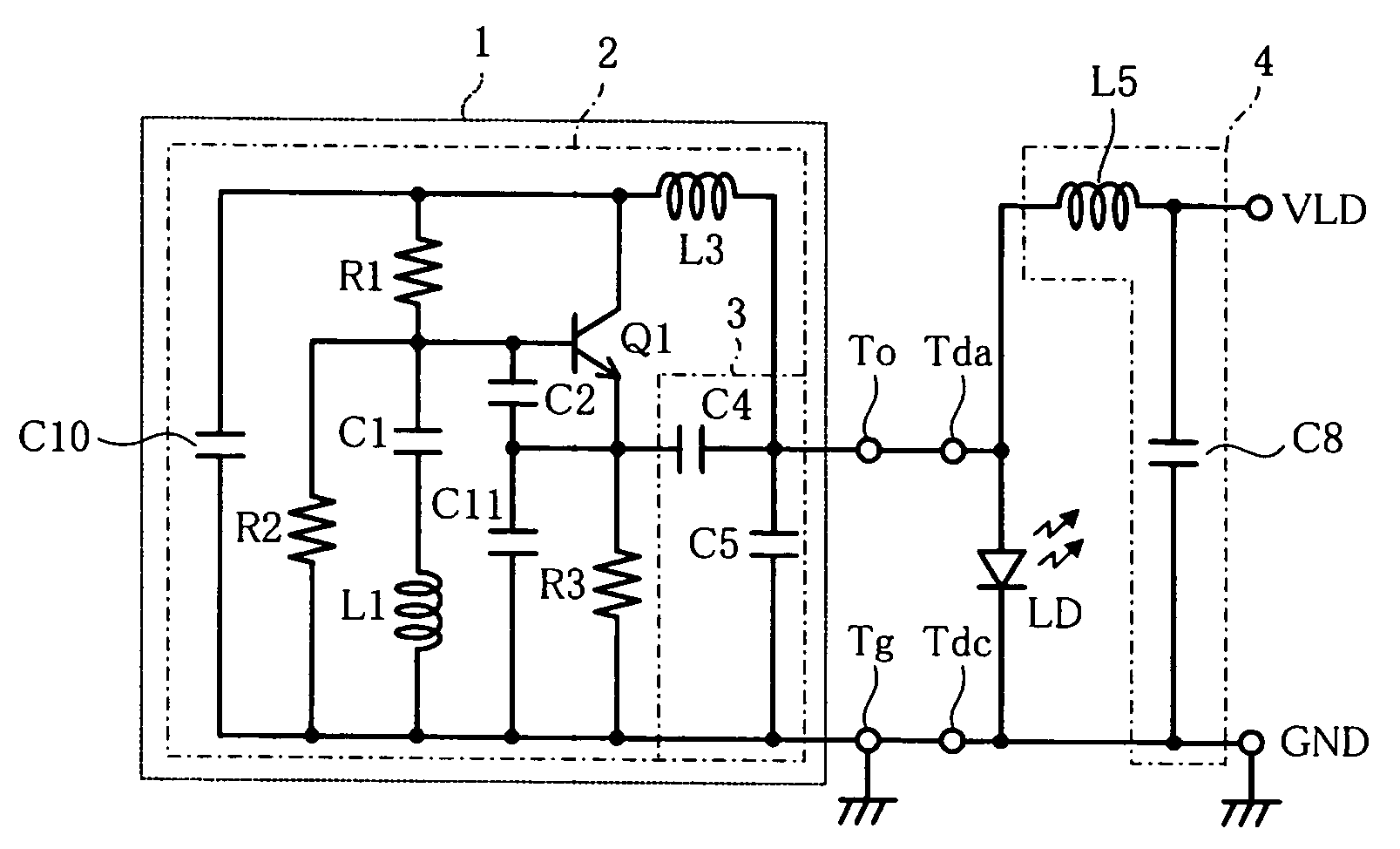
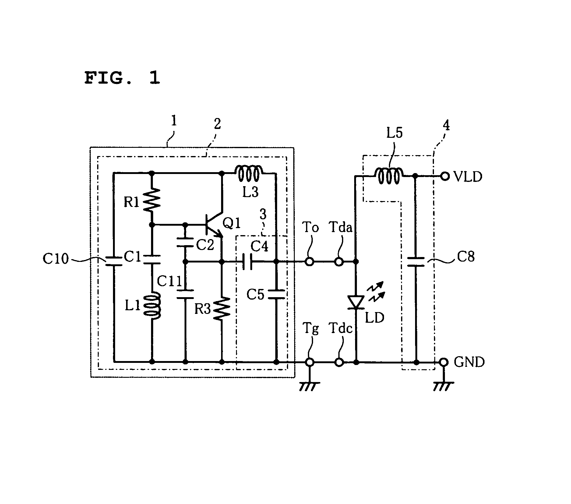
[0024]FIG. 1 is a circuit diagram of a high-frequency superposing module 1 for driving a laser diode LD according to a first preferred embodiment of the present invention. In FIG. 1, a noise suppression filter circuit 4 including a capacitor C8 and an inductor L5 is disposed between a power terminal VLD and the laser diode LD. The laser diode LD has an anode terminal Tda and a cathode terminal Tdc connected to a ground terminal GND. The high-frequency superposing module 1 has a terminal To for outputting a drive signal and a ground terminal Tg. To operate the high-frequency superposing module 1, the terminals To and Tg are connected to the terminals Tda and Tdc, respectively. If the high-frequency superposing module 1 is not connected, the laser diode LD is driven only by a DC current supplied from the power terminal VLD.

[0025]The high-frequency superposing module 1 receives a power supply therefor via the drive-signal output terminal To and also outputs a high-frequency signal to t...


PUM


Abstract

A high-frequency superposing module for driving a laser diode includes an oscillating circuit and an impedance matching circuit. The impedance matching circuit includes a capacitor connected in series between the emitter of a transistor and the terminal through which a laser-diode drive signal is output; and a capacitor connected in parallel between the drive-signal output terminal and the ground. The oscillating circuit includes an inductor serving as a choke coil connected between the drive-signal output terminal and the collector of the transistor, thus allowing the drive-signal output terminal to serve as a power input terminal for the oscillating circuit.

Description

BACKGROUND OF THE INVENTION[0001]1. Field of the Invention[0002]The present invention relates to a high-frequency superposing module for driving a laser diode by superposing a high-frequency current on a DC current.[0003]2. Description of the Related Art[0004]In a conventional laser-diode drive circuit, a laser diode is driven in a multiple mode where a high-frequency current is superposed on a driving DC current, thereby preventing the generation of mode-hopping noise resulting from an increase in the temperature of the laser diode. For superposing a high-frequency current on a DC current, an oscillating circuit that generates a high-frequency signal is used as described in, for example, Japanese Unexamined Patent Application Publication Nos. 2002-251763 and 10-256630 and Domestic Re-publication of PCT Publication No. 98 / 01856.[0005]FIG. 7 is a circuit diagram of a conventional laser-diode drive circuit disclosed in Japanese Unexamined Patent Application Publication No. 10-256630. ...

Claims


Application Information

Patent Timeline
Patent Type & Authority Patents(United States)
IPC IPC(8): H01S3/00H01S5/042H01S5/062
CPCH01S5/042H01S5/0427H01S5/02345H01S5/06226
Inventor SATOU, YOSHIROUIIDA, KAZUHIROTAMURA, MASAMICHI
Owner MURATA MFG CO LTD
Why Eureka
Try Eureka