
Software modeling of logic signals capable of holding more than two values

a logic signal and software modeling technology, applied in the field of digital system simulation, can solve the problems of inability to model complex binary gates using extended-state modeling on a typical computer workstation, inability to solve workaround solutions, and inability to meet the requirements of the verification system. to achieve the effect of efficient simulation of logic designs

Inactive Publication Date: 2006-04-18
APPLE INC
View PDF9 Cites 12 Cited by
  • Summary
  • Abstract
  • Description
  • Claims
  • Application Information

AI Technical Summary

Benefits of technology

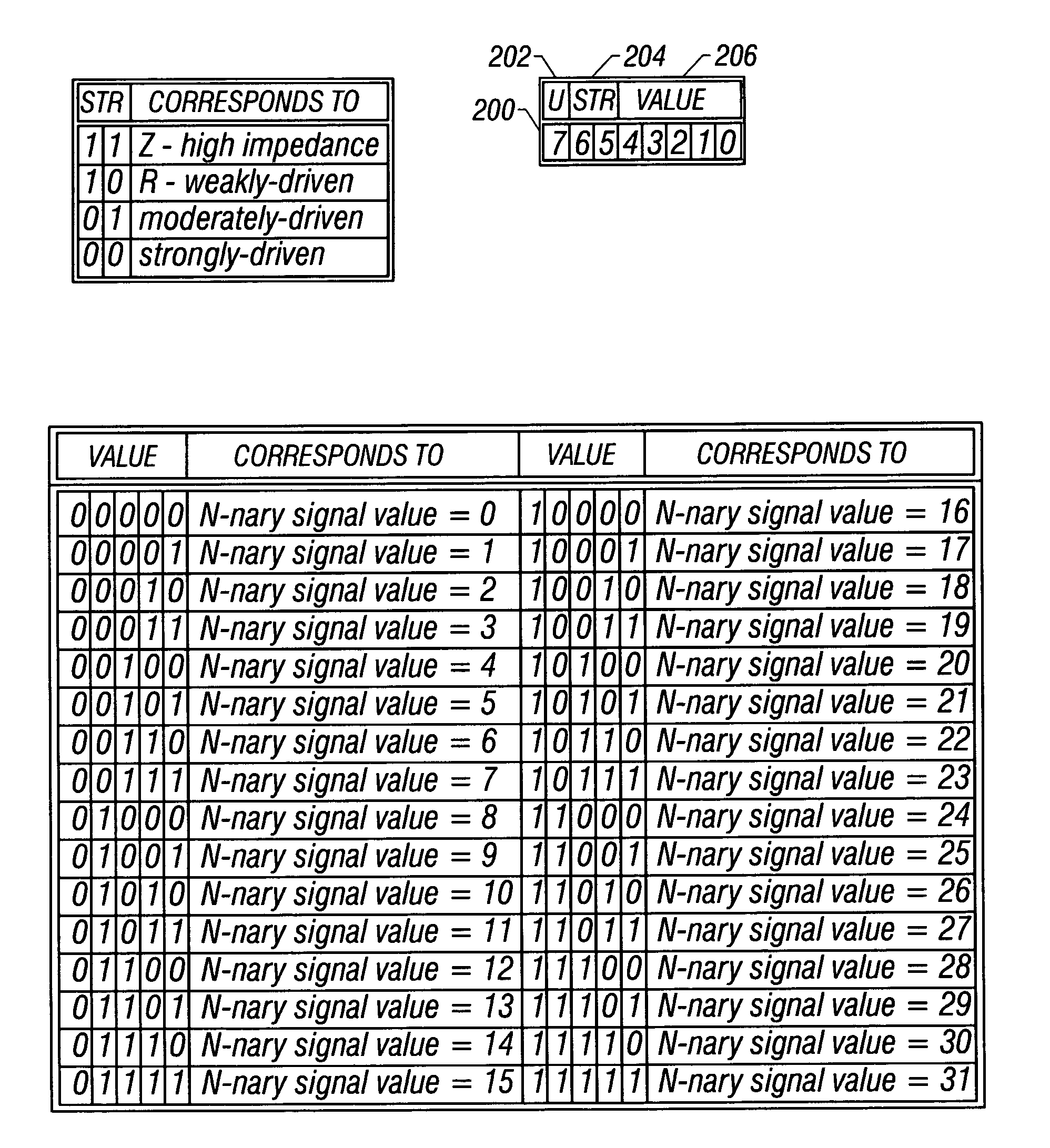
[0028]The present invention comprises a method of efficiently simulating logic designs comprising signals that are capable of having more than two unique decimal values and multiple unique drive states, such as designs based upon the new N-nary logic design style. The present invention models N-nary signals in a specific format comprising a signal value field that holds the signal's unique decimal value, a signal strength field that conveys the signal's drive state, and a signal definition field that conveys whether the signal is a defined or an undefined signal. The unique decimal value of defined signals occupies the least significant bits in the model, thus allowing the simulator to perform mathematical and logical operations on the gate's input and output signals at the signal value level, rather than at the wire / bit level.

Problems solved by technology

Designers have found that while extended-state logic simulation on a computer workstation is a powerful verification tool, it is expensive in terms of the time required to compute the various possible outputs of the design under verification, and in terms of the memory capacity required by the verification system.
As these examples demonstrate, modeling complex binary gates using extended-state modeling on a typical computer workstation quickly becomes impractical, due to memory limitations.
Nevertheless, these workaround solutions are less than ideal, and negatively impact the capability of the verification tool and the performance of the simulation itself.
Attempting to use any of these modeling tools to verify a non-binary N-nary design is complicated and inefficient.
As this example demonstrates, attempting to simulate even a few N-nary gates at this level would be far too expensive, both in terms of computation time and local workstation cache memory capacity.

Method used


Image

  • Software modeling of logic signals capable of holding more than two values
  • Software modeling of logic signals capable of holding more than two values
  • Software modeling of logic signals capable of holding more than two values

Examples


Embodiment Construction

[0039]The present invention comprises a simulation environment useful in conducting logic simulation of designs that use signals capable of holding multiple signal values, rather than being limited to 0 or 1. The present invention includes a signal modeling convention that improves memory utilization and simulation performance for a multi-state simulation, a methodology for simulating primitive logic and arithmetic functions that is much simpler and more efficient than the bit-by-bit comparison techniques employed by current binary-based simulation techniques, and a methodology for storing and producing simulation output information that is easily tailored to produce information required by the designer and to take advantage of the architecture of the simulation host. This disclosure describes numerous specific details that include specific structures, circuits, and logic functions in order to provide a thorough understanding of the present invention. One skilled in the art will app...


PUM


Abstract

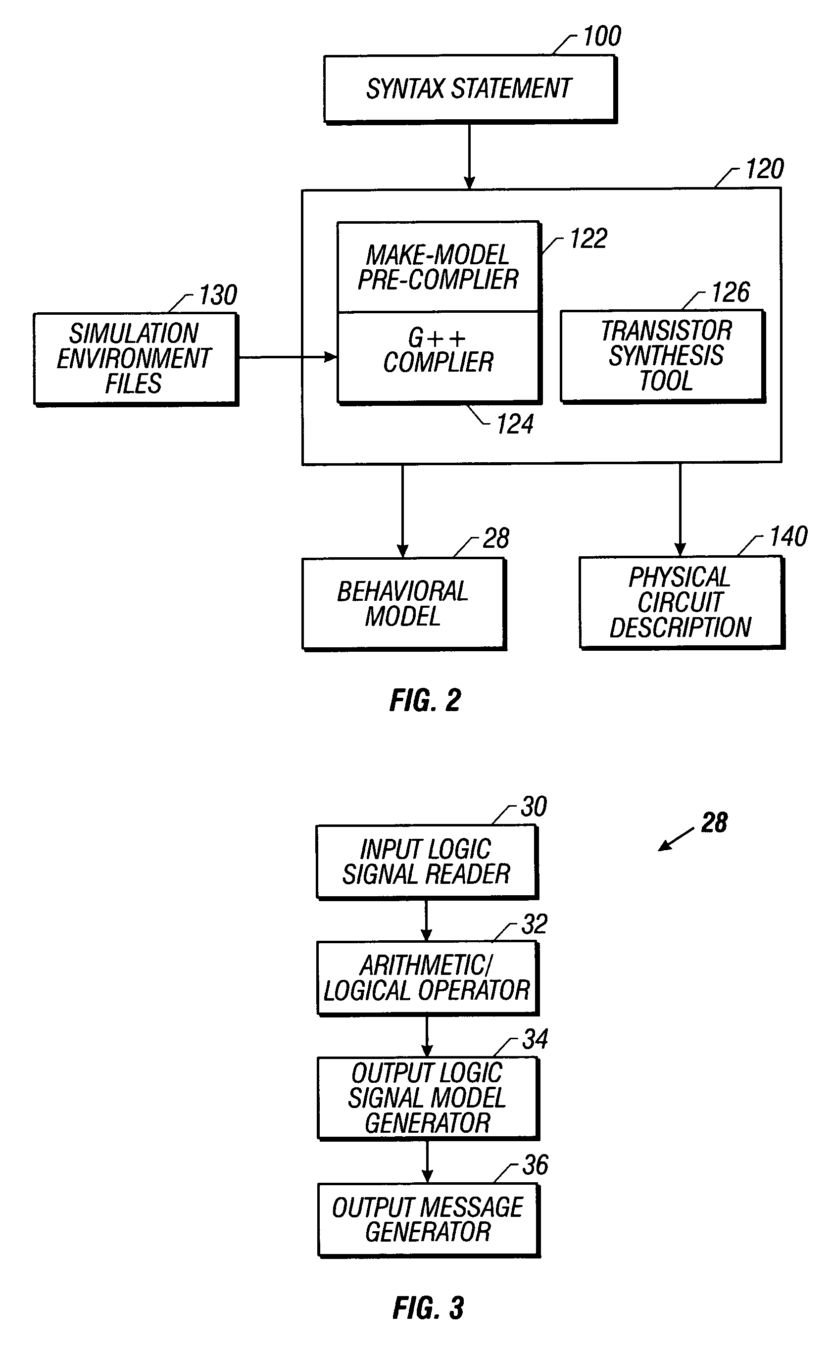
A method of efficiently simulating logic designs comprising signals that are capable of having more than two unique decimal values and one or more unique drive states, such as designs based upon the new N-nary logic design style, is disclosed. The present invention includes a signal model that models N-nary signal value, drive strength, and signal definition information in a specific format that supports the ability of the simulator to simulate the operation of the N-nary logic gates such as adders, buffers, and multiplexers by arithmetically and logically manipulating the unique decimal values of the N-nary signals. The simulator comprises an input logic signal model reader, an arithmetic / logical operator, an output logic signal model generator, and an output message generator that generates one or more output- or input-signal-specific output messages that pack relevant simulation data into a format optimized to the architecture of the simulation host.

Description

BACKGROUND OF THE INVENTION[0001]1. Field of the Invention[0002]The present invention relates to the field of digital system simulation, and more specifically, to simulating non-binary digital systems, defined as digital systems wherein input and output signals can have more than two defined logical states. In particular, the present invention provides an efficient methodology and environment for simulating digital systems designed in the N-nary logic design style.[0003]2. Description of the Related Art[0004]N-nary logic is a new dynamic logic design style fully described in a patent application, U.S. patent application Ser. No. 09 / 019,355, filed Feb. 5, 1998, now U.S. Pat. No. 6,066,965, and titled “Method and Apparatus for a N-Nary logic Circuit Using 1-of-4 Signals”, which is incorporated herein for all purposes and is hereinafter referred to as “The N-nary Patent.”[0005]Supporting a new logic design style requires the invention of new design support techniques and tools to facil...

Claims


Application Information

Patent Timeline
IPC IPC(8): G06F17/50G06F15/16
CPCG06F17/5022G06F30/33
Inventor BLOMGREN, JAMES S.BOEHM, FRITZ A.
Owner APPLE INC
Learn More