Disk cache management method of disk array device

a technology of disk array device and management method, which is applied in the direction of memory address/allocation/relocation, input/output to record carriers, instruments, etc., can solve the problems of relatively bottlenecked processing performance, rapid response, and increased processing costs, so as to improve cache page access response performance and eliminate performance bottlenecks

Inactive Publication Date: 2006-04-18
NEC CORP
View PDF8 Cites 11 Cited by
  • Summary
  • Abstract
  • Description
  • Claims
  • Application Information

AI Technical Summary

Benefits of technology

[0009]An object of the present invention is to provide a disk cache management method of a disk array device which eliminates a performance bottleneck to drastically improve cache page access response performance by thinning out the number of accesses to a shared memory involved in opening processing and closing processing of a cache page.
[0096]According to the disk cache management method of a disk array device according to the present invention, even after data transfer is completed after use of a cache page is finished which has been subjected to opening processing, the cache page in question is kept at a steady open state in which the cache page in question remains open without closing processing and when an access to the cache page in question is made by the same host director, opening processing of the cache page in question can be omitted because the cache page in question is already open. As a result, closing processing and opening processing of a cache page on a shared memory whose access time is relatively long are omitted one time each to reduce an average response time.
[0098]The above-described structure enables the host director to manage, after a cache page is used, the steady open state of the cache page in question on a cache memory in the local cache management region on the local memory without conducting processing of closing the cache page in question as a state on the shared memory. Conversely, when using a cache page at the steady open state, since it is open as a state on the shared memory, cache page opening processing is completed by the management of only a state on the local memory without changing the state on the shared memory. Also conduct LRU control of a cache page at the steady open state in order to make the number of cache pages at the steady open state be within a maximum number of pages and then in order to increase a hit rate of cache pages at the steady open state. As a result of such control, the number of accesses to the shared memory in the processing conducted at the time of cache hit can be cut off to reduce an average response time, thereby improving performance.

Problems solved by technology

The above-described conventional technique, however, only has a rapid response as compared with mechanical operation of a physical disk and depending on a load on an application of a host, a faster response might be demanded.
While time for accessing the shared memory should be inevitably increased in hardware as the disk array device is increased in scale to have the number of host directors and the capacity of the shared memory increased, port performance and director performance improve rapidly, so that the processing is relatively bottlenecking performance.
As a result, in command processing at the time of cache hit, time required for cache page opening processing and closing processing is too long to be negligible.

Method used


Image

  • Disk cache management method of disk array device
  • Disk cache management method of disk array device
  • Disk cache management method of disk array device

Examples


first embodiment

[First Embodiment]

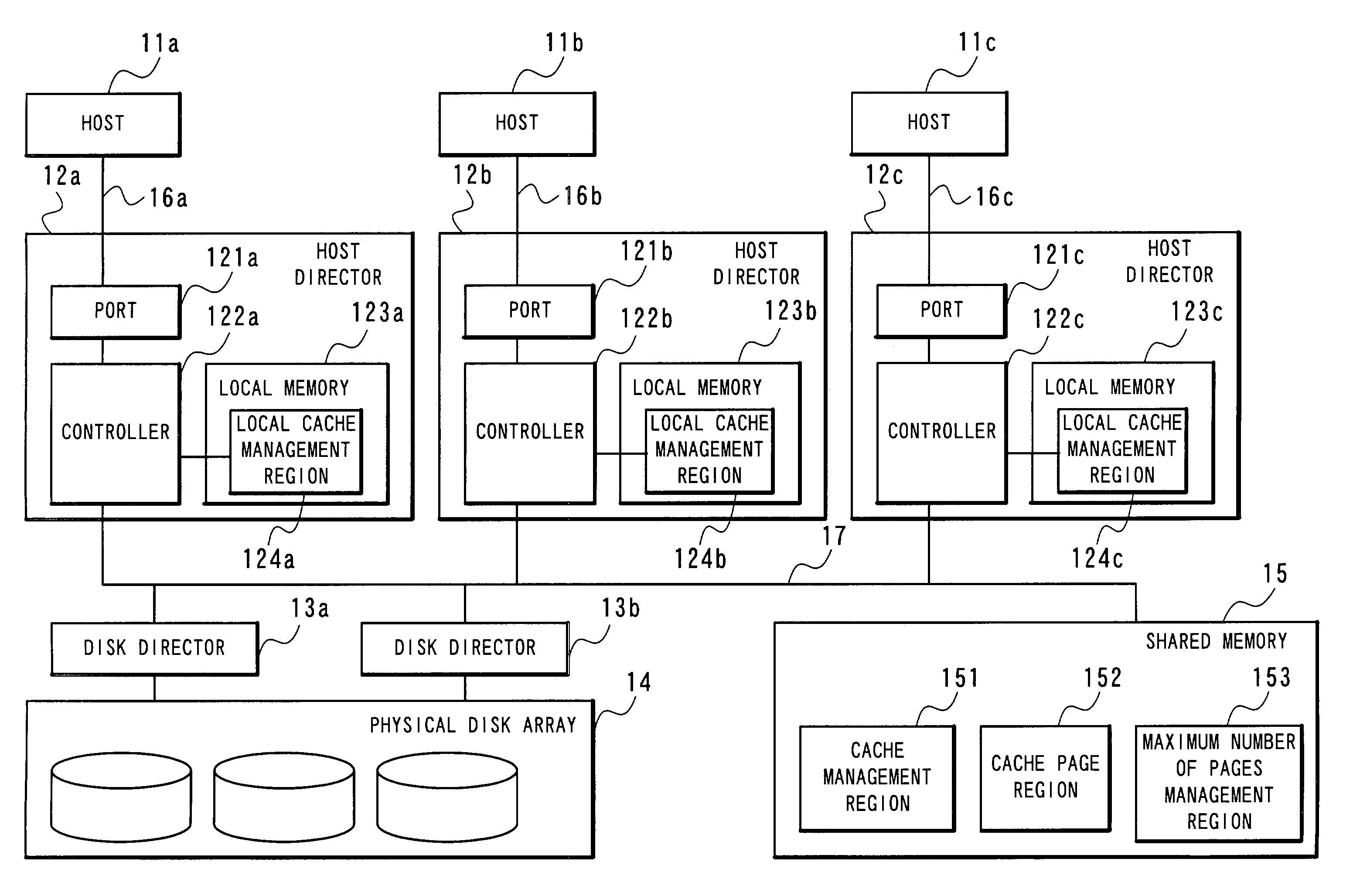
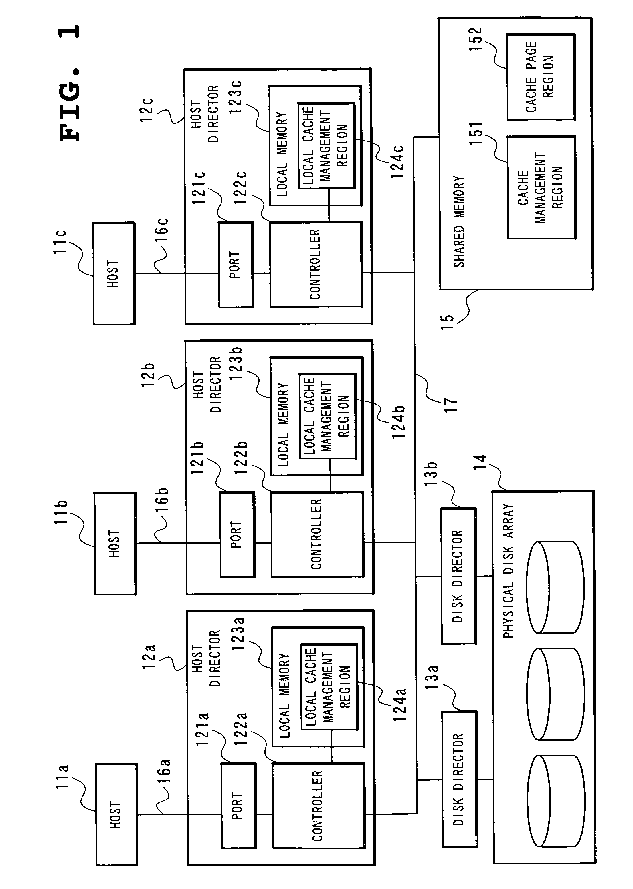
[0113]FIG. 1 is a block diagram showing a structure of a disk array device to which a disk cache management method according to a first embodiment of the present invention is applied. The disk array device includes, as main components, a plurality (three illustrated in the figure) of host directors 12a, 12b and 12c to which a plurality (three illustrated in the figure) of hosts 11a, 11b, 11c are connected through channels 16a, 16b and 16c, respectively, a plurality (two illustrated in the figure) of disk directors 13a and 13b connected to the host directors 12a, 12b and 12c through a bus 17, a physical disk array 14 connected to the disk directors 13a and 13b, and a shared memory 15 connected to the host directors 12a, 12b and 12c and the disk directors 13a and 13b through the bus 17.

[0114]The host directors 12a, 12b and 12c are composed of ports 121a, 121b and 121c, controllers 122a, 122b and 122c and local memories 123a, 123b and 123c, respectively.

[0115]The port...

second embodiment

[Second Embodiment]

[0180]Since the first embodiment is premised on that the maximum number of cache pages at the steady open state is a static basic value, fixedly used is, for example, a value obtained by evenly dividing a certain rate of the total cache pages as a maximum rate of cache pages at the steady open state by the number of host directors mounted on the disk array device. In some of disk array devices mounted with a plurality of host directors, a certain host director might not be connected or might not receive a read / write command so frequently and required performance might vary depending on a host connected. Described in the second embodiment is a method of varying a maximum number of pages at the steady open state by a host director based on a reference value set in advance and dynamically changing the maximum number of pages according to the actual number of commands received recently.

[0181]FIG. 7 is a block diagram showing a structure of a disk array device to which...

third embodiment

[Third Embodiment]

[0184]FIG. 9 is a block diagram showing a structure of a disk array device to which a disk cache management method according to a third embodiment of the present invention is applied. The disk array device differs from the disk array device shown in FIG. 1 to which the disk cache management method according to the first embodiment is applied only in further including host director programs 100 for the respective host directors 12a, 12b and 12c of the disk array device.

[0185]The host director program 100 is read into each of the host directors 12a, 12b and 12c to control operation of each of the host directors 12a, 12b and 12c completely in the same manner as that for the operation of the host directors 12a, 12b and 12c according to the first embodiment. Therefore, no detailed description will be made of operation of the disk array device to which the disk cache management method according to the third embodiment is applied.


PUM


Abstract

A local memory mounted on a host director is provided with a local cache management region for managing a cache page at a steady open state in a cache management region on a shared memory, so that even after data transfer is completed after the use of a cache page on the shared memory subjected to opening processing is finished, the cache page in question is kept open at the steady open state without closing the cache page in question and when an access to the cache page in question is made from the same host director, processing of opening the cache page in question is omitted to improve response performance.

Description

BACKGROUND OF THE INVENTION[0001]1. Field of the Invention[0002]The present invention relates to a disk cache management method of a disk array device and, more particularly, to a disk cache management method of a disk array device mounted with a plurality of host directors (also called host adaptor) and a memory serving as a disk cache shared by these host directors (hereinafter referred to as shared memory).[0003]2. Description of the Related Art[0004]A disk array device mounted with a plurality of host directors in general has a shared memory of a large capacity mounted thereon for use as a disk cache. When a read command received from a host computer (hereinafter simply referred to as host) hits the cache, data can be transferred to the host without mechanical operation of a physical disk, so that a rapid response is possible. Also when receiving a write command, a fast response is enabled by ending the write command at a time when data is written to the disk cache and then writ...

Claims


Application Information

Patent Timeline
Patent Type & Authority Patents(United States)
IPC IPC(8): G06F12/00G06F3/06G06F12/08G06F12/12
CPCG06F12/0866G06F2212/312
Inventor KUWATA, ATSUSHI
Owner NEC CORP
Why Eureka
Try Eureka