Plural station memory data sharing system

Inactive Publication Date: 2006-04-18
STEP TECHNICA +1
View PDF8 Cites 29 Cited by
  • Summary
  • Abstract
  • Description
  • Claims
  • Application Information

AI Technical Summary

Benefits of technology

[0026]When the memory-type station device or the I/O-type station device for the system for sharing memory data of

Problems solved by technology

In the case of this electronic wired system, however, there is a problem that a given terminal device cannot read data from the input/output port of another terminal device or write data into such port, although the central unit 1 can read/write data at the output/in

Method used


Image

  • Plural station memory data sharing system
  • Plural station memory data sharing system
  • Plural station memory data sharing system

Examples


first embodiment

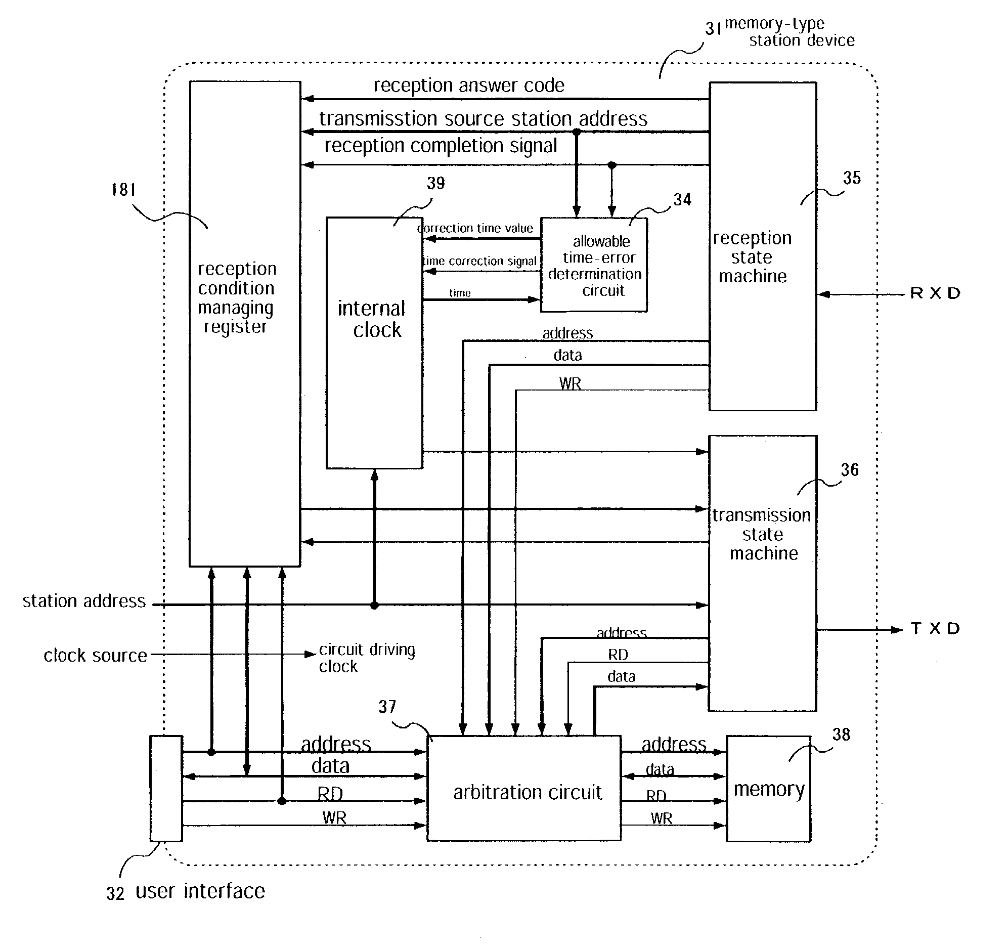
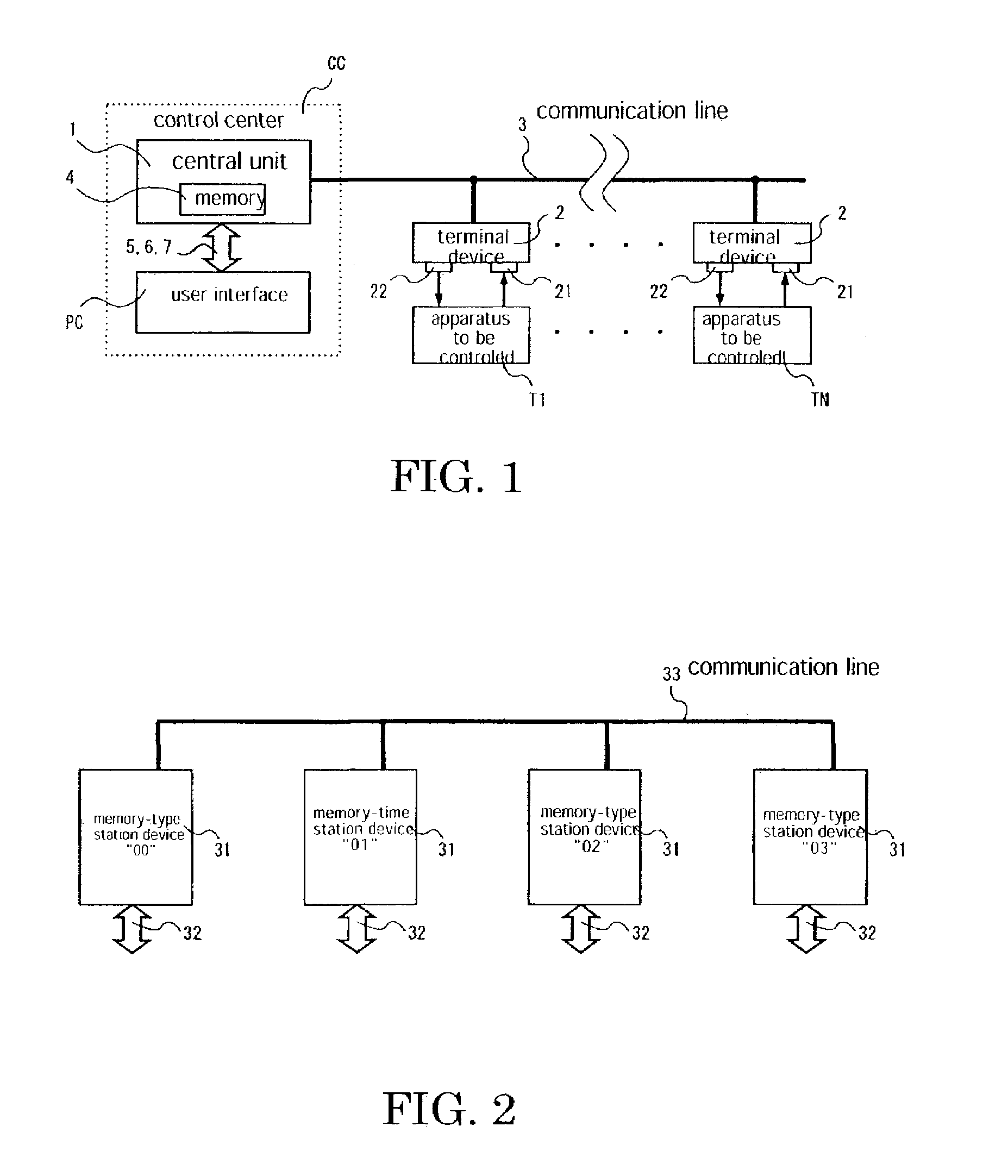
[0046]A system for sharing memory data of a plurality of stations according to a first embodiment of the invention is a system in which each station is composed only of a memory-type station device 31 (see FIG. 2).

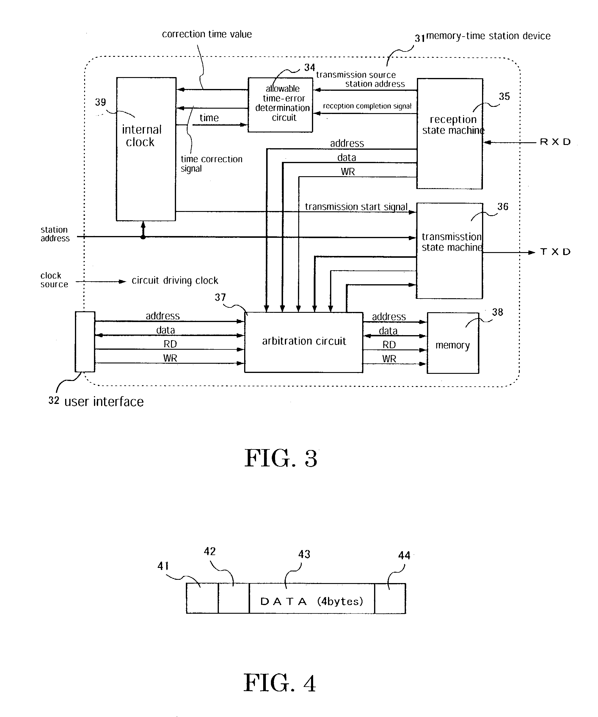
[0047]Each memory-type station device 31 is formed by a semiconductor integrated circuit and comprises, as shown in FIG. 3, a user interface 32, an allowable time-error determination circuit 34, a reception state machine 35, a transmission state machine 36, an arbitration circuit 37, a memory 38 and an internal clock 39, all of which are constituted by digital circuits each driven by a circuit-driving clock from a clock source.

[0048]The internal clock 39 is constituted by an incrementing counter circuit in which its count value is increased from “0” and returned to “0” upon reaching the upper limit time “TM” defined specifically to this system, whereby its time is advanced cyclically. When the time instant indicated by the internal clock 39 agrees to the time instant corre...

second embodiment

[0070]A system for sharing memory data of a plurality of stations according to a second embodiment is a system which comprises two stations each composed of the memory-type station device 31 and two stations each composed of an I / O-type station device 91 (see FIG. 8).

[0071]Each I / O-type station device 91 is formed by a semiconductor integrated circuit and comprises, as shown in FIG. 9, an I / O terminal output port 92, an I / O terminal input port 93, an output address setting circuit 94, an output-port data holding circuit 95, a transmission state machine 36, a reception state machine 35, an internal clock 39 and an allowable time-error determination circuit 34, all of which are constituted by digital circuits each driven by a circuit-driving clock from a clock source.

[0072]Unlike the memory-type station device 31, this I / O-type station device 91 does not comprise the memory 38 and the arbitration circuit 37. The reception state machine 35, the internal clock 39 and the allowable time-...

third embodiment

[0083]A system for sharing memory data of a plurality of stations according to a third embodiment is a system in which the number of packets which each station can transmit in succession can be set. According to this system, when the internal clock indicates the time instant which corresponds to the station address value of the own station, packets equal in number to a number set to a packet transmission number determination circuit are transmitted in succession.

[0084]A memory-type station device 31 used in this system is formed by a semiconductor integrated circuit, and its structure is as shown in FIG. 10. As compared to the device of the first embodiment shown in FIG. 3, the transmission state machine 36 is added with a packet transmission number determination circuit 101.

[0085]When the internal clock 39 indicates a time instant which corresponds to the station address value of the own station, the transmission state machine 36 transmits, in succession, packets equal in number to...


PUM


Abstract

A plural station memory data sharing system in which packets are sent/received between plural stations interconnected through communication lines. Each station has a unique station address value, and the time is made to correspond to each station address value. The internal clock (39) in each station indicates the same time and circulates from time T00 to an upper limit time TM. When the internal clock (39) indicates a time corresponding to the station address value of a station, data stored in a memory at the address position corresponding to the station address value is buried in a packet and the packet is sent through a communication line. An allowance time error sensing circuit (34) compares the calculated correct time of the internal clock of the station and the time indicated by the internal clock, If the error is out of an allowance range, the internal clock (39) is forcedly calibrated to the correct time.

Description

TECHNICAL FIELD[0001]This invention relates to a system for sharing memory data of a plurality of stations in which all the stations can share the same memory data.BACKGROUND ART[0002]One of the joint applicants of the present application, STEP TECHINICA Co. Ltd., filed a patent application relating to “an electronic wired system based on automatic cyclical communication” which has been granted as a patent under No. 2,994,589. This patent will be described with reference to FIG. 1. This electronic wired system is constituted by N sets of terminal devices 2, a central unit 1 for controlling the terminal devices 2 and a common communication line 3 connecting these together. Data at an input port 21 and an output port 22 of each terminal device 2 is circulated through the terminal devices in the form of packets and stored in a memory 4 of the central unit 1 at a respective one of memory locations having addresses which correspond to the terminal devices, respectively. In this electroni...

Claims


Application Information

Patent Timeline
IPC IPC(8): G06F12/00H04L12/40G06F15/17G06F1/14G06F13/00G06F15/167G06F15/177H04J3/06H04L12/28H04L12/417H04L29/06
CPCH04J3/0652H04L69/28H04L12/417H04L12/40
Inventor MUGITANI, TOMIHIRONATSUI, TOSHIKI
Owner STEP TECHNICA
Why Eureka
Try Eureka