Pipe bending processing apparatus and pipe bending processing method

a processing apparatus and pipe bending technology, applied in the field of pipe bending processing apparatus and pipe bending processing method, to achieve the effects of improving material yield and workability, reducing man-hours, and improving yield ra

Active Publication Date: 2006-04-25
CALSONIC KANSEI CORP
View PDF9 Cites 9 Cited by
  • Summary
  • Abstract
  • Description
  • Claims
  • Application Information

AI Technical Summary

Benefits of technology

[0014]According to the second aspect of the invention, since there is no need to set an extrusion margin for avoiding interference between the compression bending mold and the side bending mold in the end of the pipe, a yield rate can be improved. Further, a step of cutting an unnecessary portion of the extrusion margin becomes unnecessary, so that the number of man-hours can be reduced.
[0015]Furthermore, a side bending mold in which a plurality of stoppers are provided is used and when the side bending mold is pressingly contacted with a pipe, a pipe axial position of the side bending mold is set according to a length of the pipe and thereby, for pipes with the same diameter, processing can be performed continuously without replacing the side bending mold. Therefore, further improvements in material yield and workability can be achieved.

Problems solved by technology

Therefore, in the case that a bending processing part of a pipe to be processed is near to the end and the compression bending mold interferes with the side bending mold when compression bending processing and side bending processing are performed with respect to the pipe, the stopper of the side bending mold is engaged with the end of the pipe and the side bending mold and the drawing and bending mold are actuated and thereby the stopper pressurizes the end of the pipe in a movement direction of the side bending mold, so that the side bending processing and the compression bending processing are simultaneously performed by the side bending mold.

Method used


Image

  • Pipe bending processing apparatus and pipe bending processing method
  • Pipe bending processing apparatus and pipe bending processing method
  • Pipe bending processing apparatus and pipe bending processing method

Examples


first embodiment

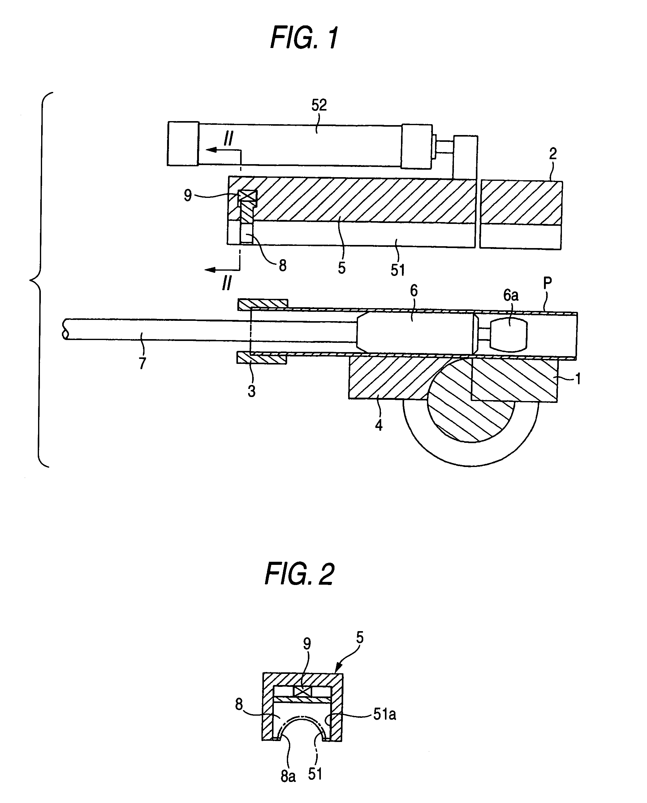
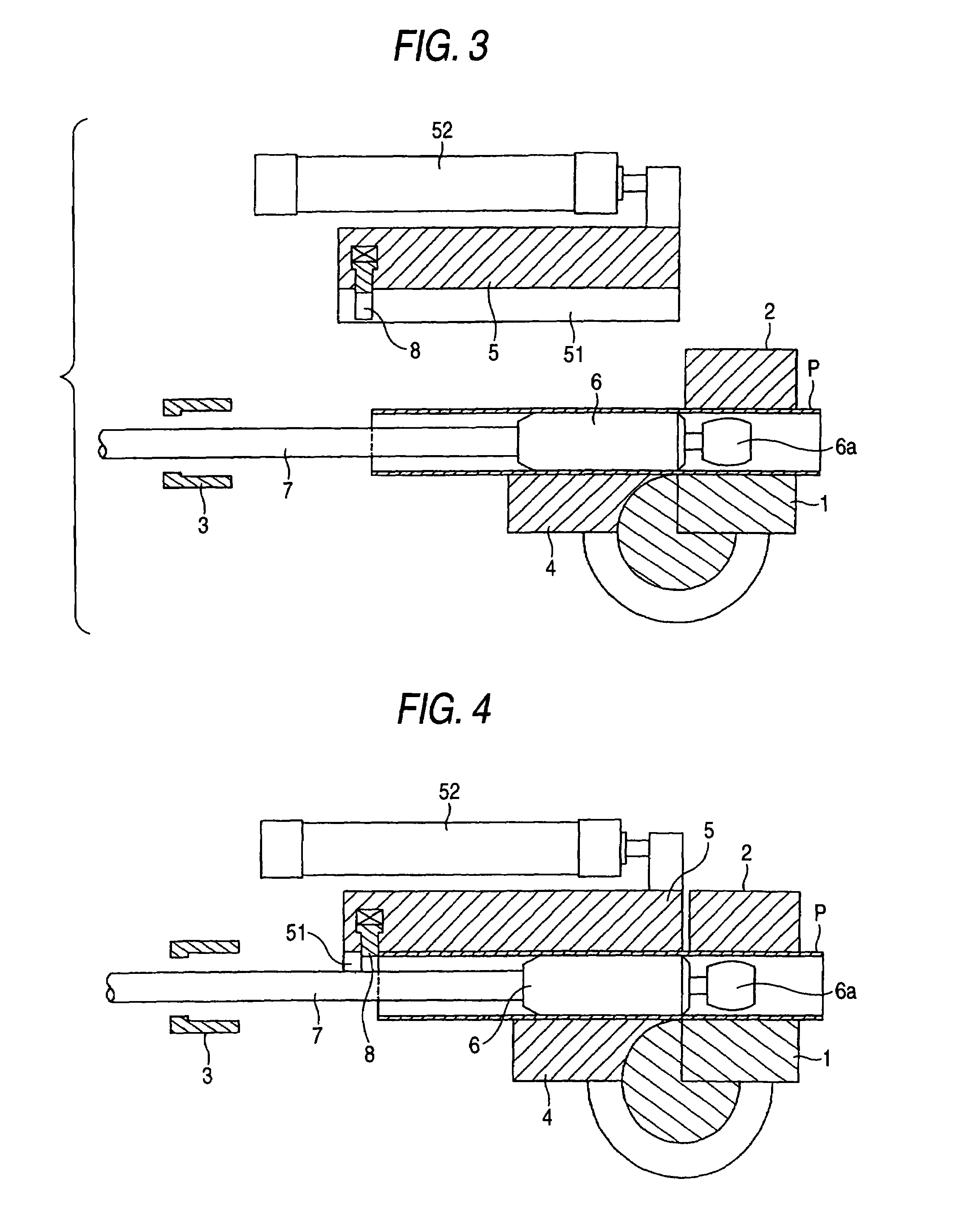
[0029]FIG. 1 is a sectional view showing a first embodiment of a pipe bending processing apparatus of the invention.

[0030]In FIG. 1, P is a pipe, numeral 1 is a drawing and bending mold, numeral 2 is a clamp mold, numeral 3 is a chuck, numeral 4 is a wiper, numeral 5 is a side bending mold, and numeral 6 is a mandrel.

[0031]The drawing and bending mold 1 tightens and fixes one end of the pipe P along with the clamp mold 2. The drawing and bending mold 1 rotates by a cylinder (not shown) for drawing and bending and performs drawing and bending processing of the pipe P.

[0032]The chuck 3 tightens and fixes the other end of the pipe P. The chuck 3 moves in a pipe axis direction by a cylinder (not shown) for compression bending and performs compression bending processing of the pipe P.

[0033]The wiper 4 and the side bending mold 5 tighten and fix the side of the pipe P. The wiper 4 is fixed, and the side bending mold 5 moves in the pipe axis direction by a cylinder 52 for side bending and ...

second embodiment

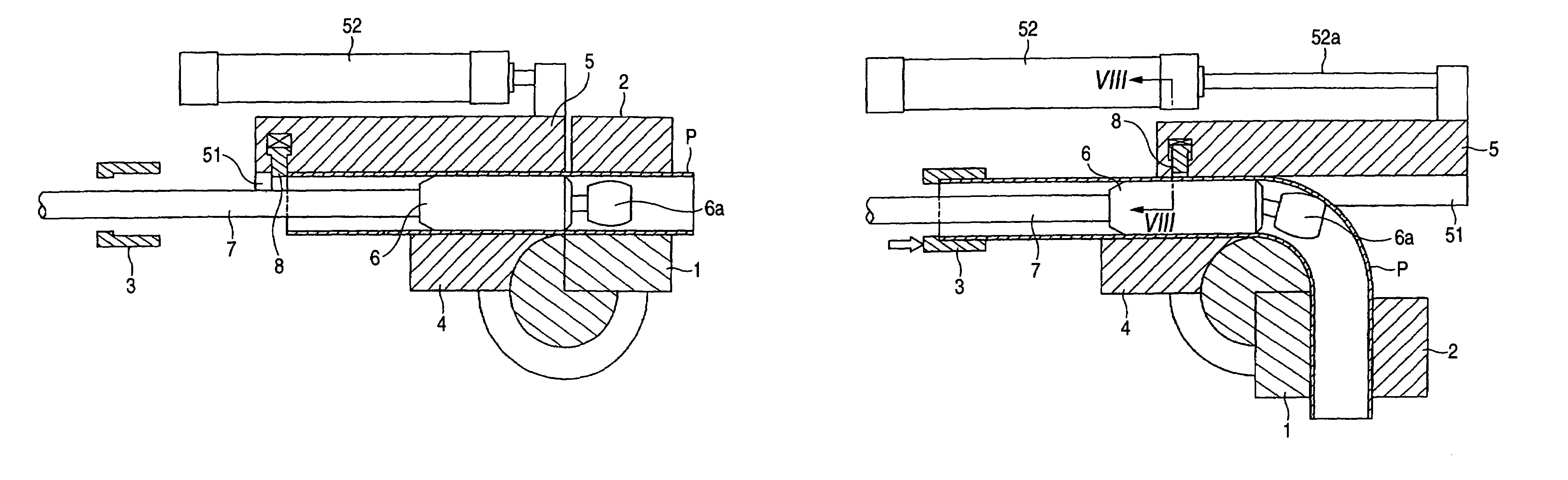
[0051]FIG. 9 is a sectional view showing a second embodiment of a pipe bending processing apparatus of the invention. Incidentally, the second embodiment differs from the first embodiment in that a plurality of stoppers are provided in a length direction of a pipe.

[0052]That is, a pipe pressingly contact surface 51 in the vicinity of the back end of the side bending mold 5 is provided with stoppers 80a to 80d. As a spacing of these stoppers 80a to 80d, a spacing in which a gap between the side bending mold 5 and a clamp 2 does not influence bending, for example, the order of 10 mm to 30 mm is suitable.

[0053]The side bending mold 5 can adjust a pipe pressingly contact position according to a length of a pipe P by a cylinder 52 for side bending in which NC (numerical control) is performed. That is, it is set so that any one of the stoppers 80a to 80d aligns with an end position of the pipe P by inputting a length of the pipe P to be processed to an NC machine previously.

[0054]As descr...


PUM

PropertyMeasurementUnit
lengthaaaaaaaaaa
angleaaaaaaaaaa
structureaaaaaaaaaa

Abstract

A pipe bending processing apparatus includes a drawing and bending section for pressingly contacting a drawing and bending mold, a clamp mold with one end of a pipe P and performing drawing and bending processing, compression bending section for pressingly contacting a chuck with the other end of the pipe and performing compression bending processing, side bending section for pressingly contacting a wiper, and a side bending mold with the side of the pipe and performing side bending processing. The side bending mold provides a stopper 8 which advances and retracts from a pipe pressingly contact surface and engages with the other end of the pipe.

Description

[0001]The present disclosure relates to the subject matter contained in Japanese Patent Application No. 2002-071153 filed on Mar. 15, 2002, and in Japanese Patent Application No. 2002-196864 filed on Jul. 5, 2002, which are incorporated herein by reference in its entirety.BACKGROUND OF THE INVENTION[0002]1. Field of the Invention[0003]The present invention relates to a technical-field of a pipe bending processing apparatus and a pipe bending processing method suitable to perform small radius bending processing of a pipe.[0004]2. Description of the Related Art[0005]As the conventional art of this kind, the art described in JP-A-61-222634 (JP-B-2-015291) has been known. This conventional art has a structure as shown in FIG. 10.[0006]As shown in FIG. 10, one end of a pipe P is tightened and fixed by a clamp mold 102 in a drawing and bending mold 101 for performing drawing and bending processing. The drawing and bending mold 101 rotates by a cylinder (not shown) for drawing and bending ...

Claims


Application Information

Patent Timeline
Patent Type & Authority Patents(United States)
IPC IPC(8): B21D7/025B21D9/07B21D9/05
CPCB21D9/07
Inventor HATANO, YASUJI
Owner CALSONIC KANSEI CORP
Why Eureka
Try Eureka