Quick-extraction punch-holder adapter for converting punching machines from a single-punch to a multiple-punch configuration

Inactive Publication Date: 2006-04-25
EUROMAC SPA
View PDF29 Cites 33 Cited by
  • Summary
  • Abstract
  • Description
  • Claims
  • Application Information

AI Technical Summary

Benefits of technology

[0011]A first aim of the present invention is to obviate the above-noted drawbacks of the punching machines of the prior art by providing a quick-extraction multiple punching head for converting a punching machine from a single-punch to a multiple-punch configuration. The multiple punching head of th

Problems solved by technology

Moreover, it should be noted that punches wear out over time and, in order to be used for longer periods, they are subjected to grinding or sharpening operations which cause variations in their overall useful length.
The above-described prior art suffers from some drawbacks.
A first drawback is the fact that replacement of a punch is relatively complicated and time-consuming.
A second drawback is that the extraction force exerted by the return springs is rather limited.
Thus, it may happen that after an active descent of the punch, the punch is held jammed in a just perforated metal plate, consequently requiring that an operator manually release the punch from the metal plate by usin

Method used


Image

  • Quick-extraction punch-holder adapter for converting punching machines from a single-punch to a multiple-punch configuration
  • Quick-extraction punch-holder adapter for converting punching machines from a single-punch to a multiple-punch configuration
  • Quick-extraction punch-holder adapter for converting punching machines from a single-punch to a multiple-punch configuration

Examples


Embodiment Construction

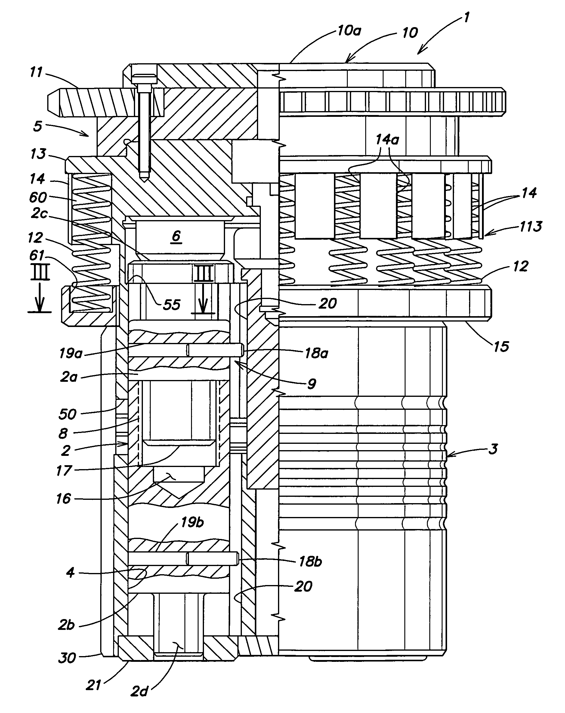
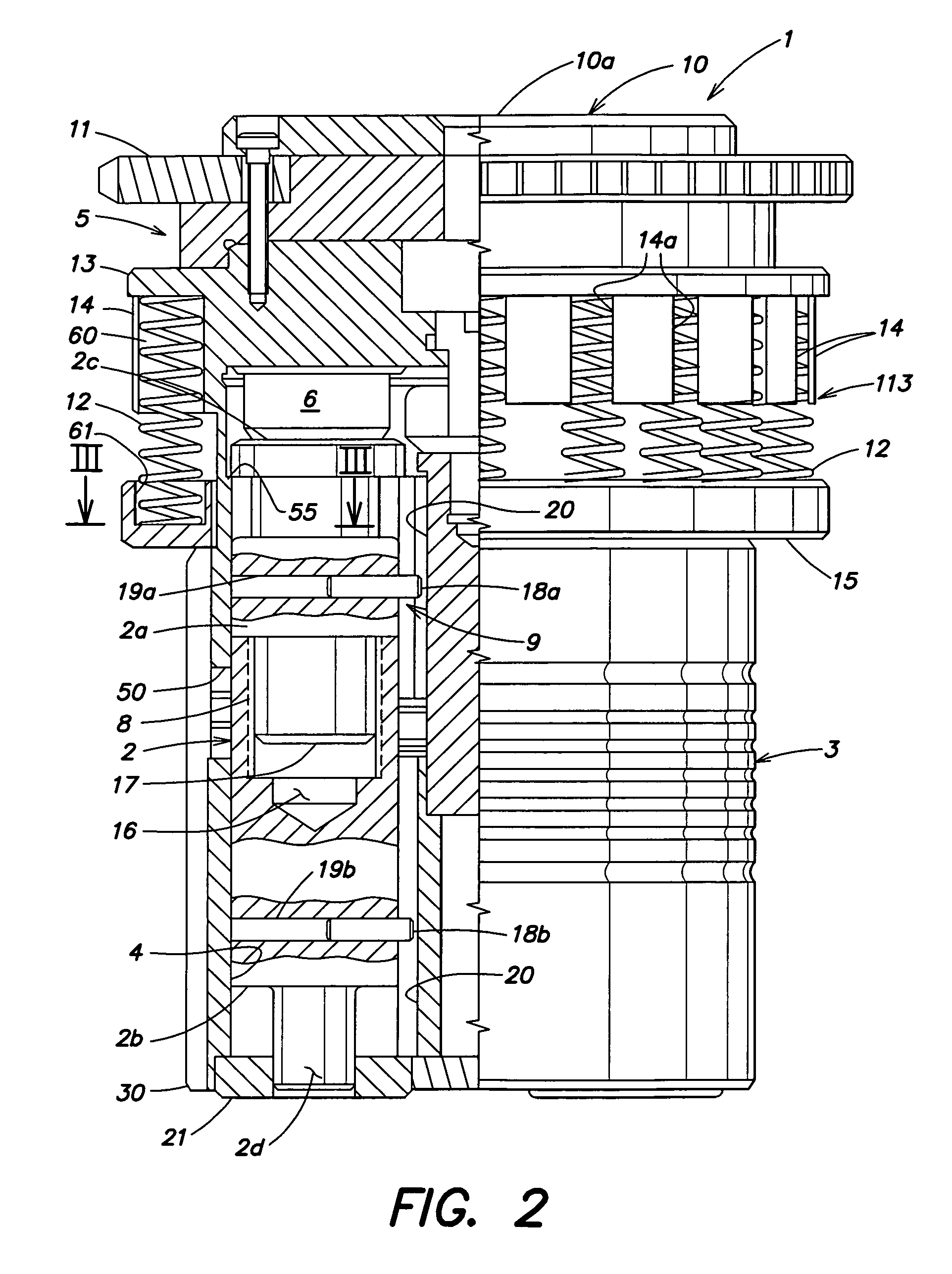
[0022]With reference to the above FIGS. 1 to 6, numeral 1 designates a quick-extraction multiple punching head for converting a punching machine from a single-punch to a multiple-punch configuration. Punching head 1 comprises a cylindrical body 3 which is provided on its outer surface with a rib 30. The cylindrical body 3 is located in an outer casing 25. The outer casing 25 is provided with a slot adapted to receive the rib 30 for preventing rotation of the cylindrical body 3. The punching head is formed with a plurality of seats 4, e.g., four in number, each being designed to locate the axis of a respective punch 2 parallel to the axis of the cylindrical body 3.

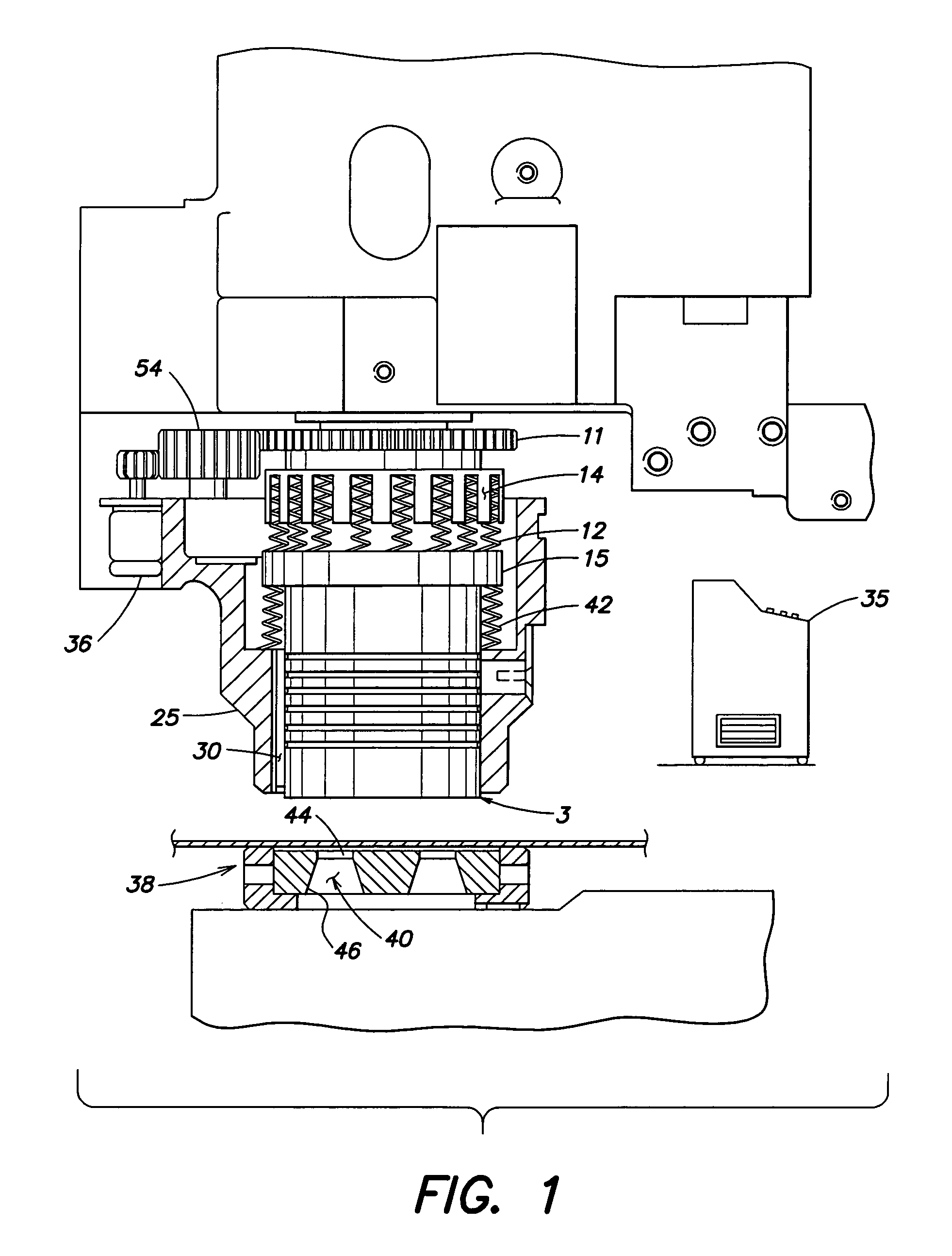
[0023]At one end of the cylindrical body 3 there is provided a rotatably fitted selection group 5 which is provided on its lower face with a pusher 6 in contact with the head 2c of a respective punch 2. As shown in FIG. 1, the selection group 5 can be conveniently coupled to a motor 36 controlled by suitable control unit 35...


PUM

PropertyMeasurementUnit
Resilienceaaaaaaaaaa

Abstract

A punching machine comprising at least one punching head including a support body having a first end delimiting a peripheral shoulder, a second end, and at least two parallel seats being angularly spaced from one another and extending through said support body from said first end to said second end; a punching tool holder slibably mounted in at least one of said seats; a multiplicity of removable resilient means angularly spaced from one another, each having a first end resting on said peripheral shoulder and a second end facing away from said peripheral shoulder; an annular cap member arranged in front and spaced from said peripheral shoulder and designed to abut against said second end of said resilient means; a rotor member mounted for rotation on said annular cap member and having an inner face thereof facing towards said punching tool holder; a sliding member projecting from said inner face and arranged to slide onto said punching tool holder when said rotor member rotates; and driving means designed to stepwise drive said rotor member, whereby locating said sliding member onto a pre-selected punching tool holder.

Description

[0001]This is a continuation-in-part of Application No. 09 / 843,988, filed Apr. 27, 2001, now abandoned, the disclosure of which is expressly incorporated herein by reference.BACKGROUND OF THE INVENTION[0002]The present invention relates to a quick-extraction multiple punching head for converting punching machines from a single-punch to a multiple-punch configuration.[0003]It is well-known that punching machines employed to machine metal plates use bodies, known as punch-holders, for accommodating the punches. The punches are located within the punch holder below the hammer, and, when struck by the hammer, the punches move over a stroke of a preset extent, allowing the metal plate to be worked.[0004]Such punch-holders generally consist of a cylindrical body formed with a through seat accommodating the punch that is used for a given punching operation, so as to accommodate only one punch at a time. A horizontal disk-shaped member is mounted above the cylindrical body, such that it can...

Claims


Application Information

Patent Timeline
IPC IPC(8): B26F1/14B26D5/08B21D28/12B21D28/34B21D37/04
CPCB21D28/12B21D37/04B21D28/34B21D28/125Y10T83/8727Y10T83/8749Y10T83/944Y10T83/8732
Inventor OSTINI, GIORGIO
Owner EUROMAC SPA
Why Eureka
Try Eureka