Thin film forming apparatus and method

a film forming apparatus and film technology, applied in the direction of individual semiconductor device testing, semiconductor/solid-state device testing/measurement, instruments, etc., can solve the problems of apparatus failure to maintain a vacuum degree in the chamber, unstable state, and difficulty in taking care of changes in various sputtering conditions during sputtering steps, etc., to achieve efficient formation

Inactive Publication Date: 2006-04-25
ULVAC INC
View PDF4 Cites 22 Cited by
  • Summary
  • Abstract
  • Description
  • Claims
  • Application Information

AI Technical Summary

Benefits of technology

[0014]The film formation rate controlling member has two or more openings which are different each in area and each of the openings can be selected in the order of the scale of the area of the opening. Then, each opening is to be selected to efficiently control the film formation rate.
[0030]In this case, the film forming apparatus further comprises metal film forming means using the sputtering gas comprising rare gas to sputter target metal of the sputtering cathode to form a metal thin film on the substrate and oxidizing or nitriding means for oxidizing or nitriding the metal thin film formed on the substrate using the reactive gas. This apparatus is allowed to divide sputtering region and reaction region, thereby enabling a dielectric thin film to be more efficiently formed.

Problems solved by technology

However, with a shutter (film thickness correcting plate) having an opening with a fixed shape, it is difficult to take care of changes in various sputtering conditions during sputtering step (the vacuum degree, the amount of gas introduced, the amount of gas released from the chamber, the sputtering voltage, the sputtering current and the like).
Furthermore, the hysteresis curve changes markedly at the time of input electric power, resulting in an unstable state.
However, this apparatus may fail in maintaining a vacuum degree in the chamber when a driving work for the film thickness correcting plates is carried out.
Consequently, this apparatus cannot be efficient from the handling point of view.

Method used


Image

  • Thin film forming apparatus and method
  • Thin film forming apparatus and method
  • Thin film forming apparatus and method

Examples


example 1

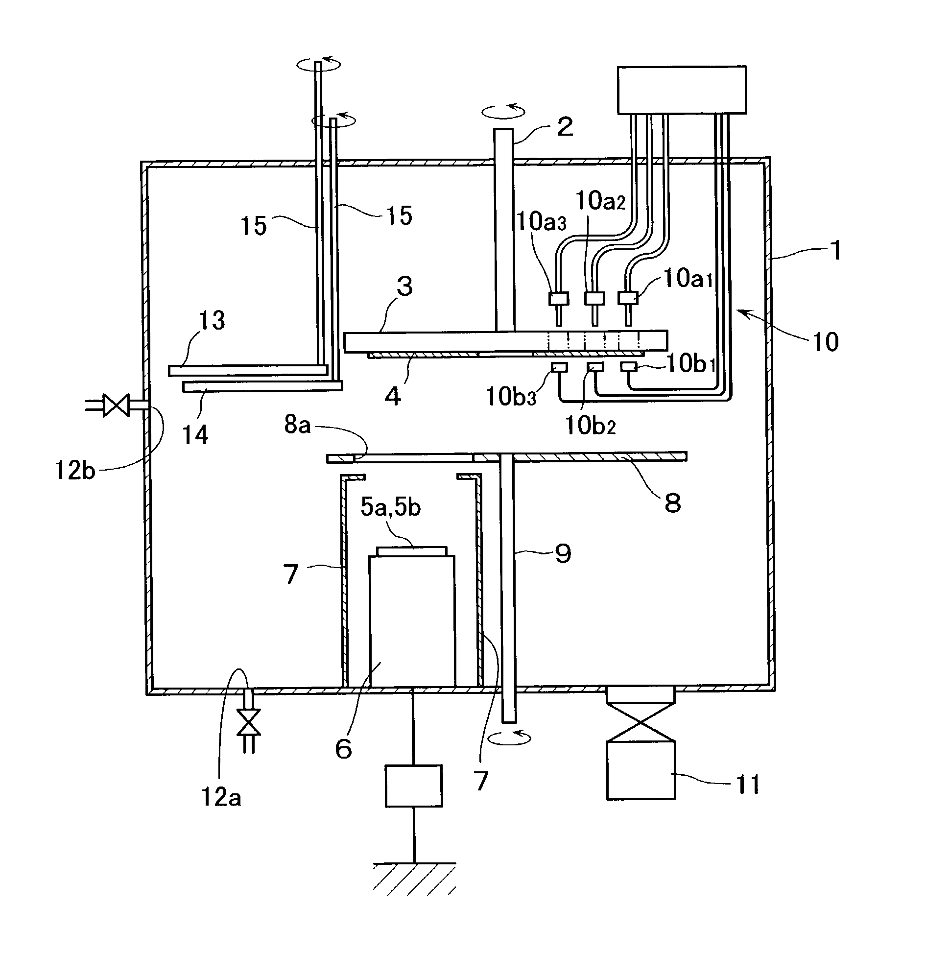
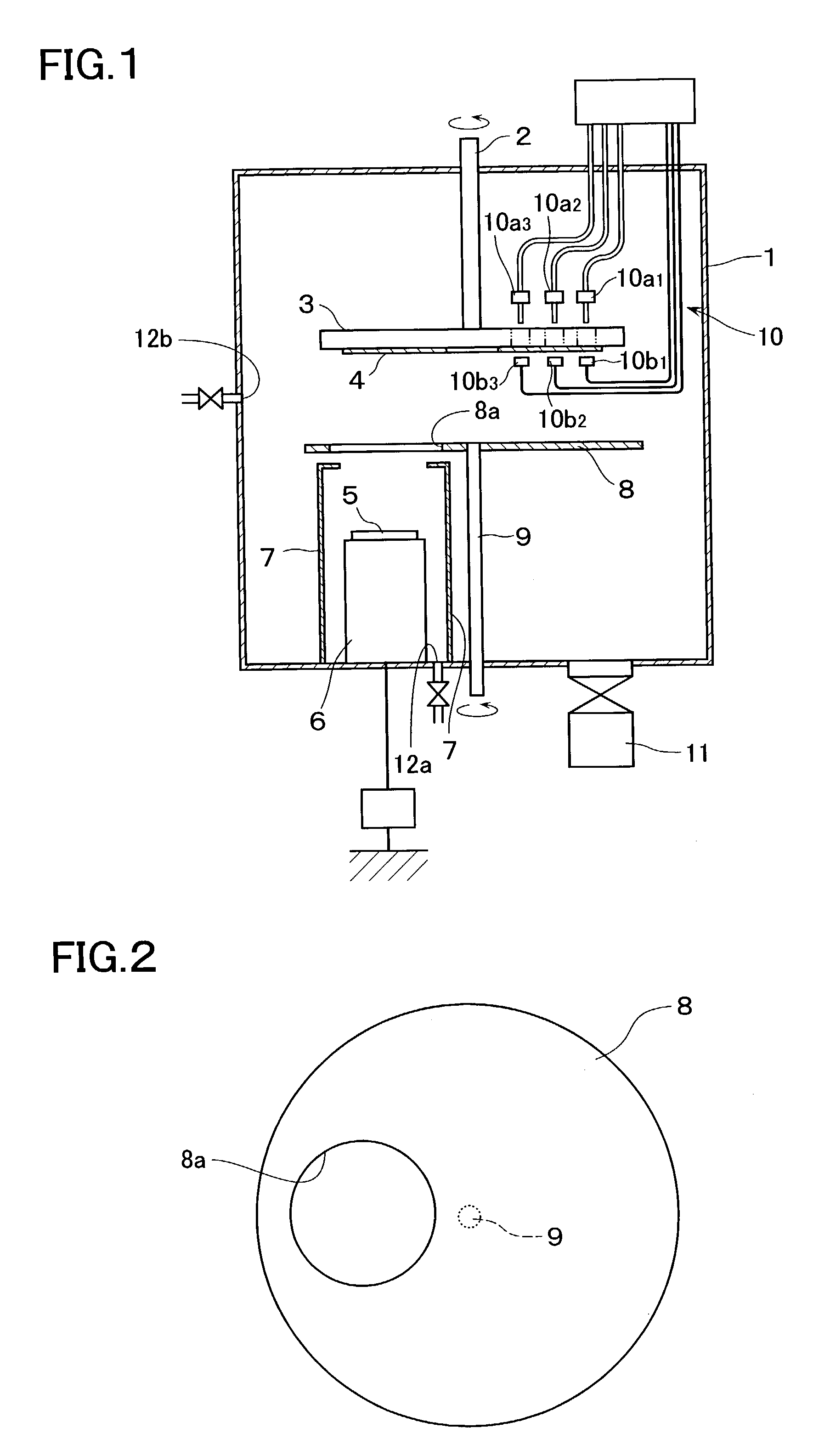
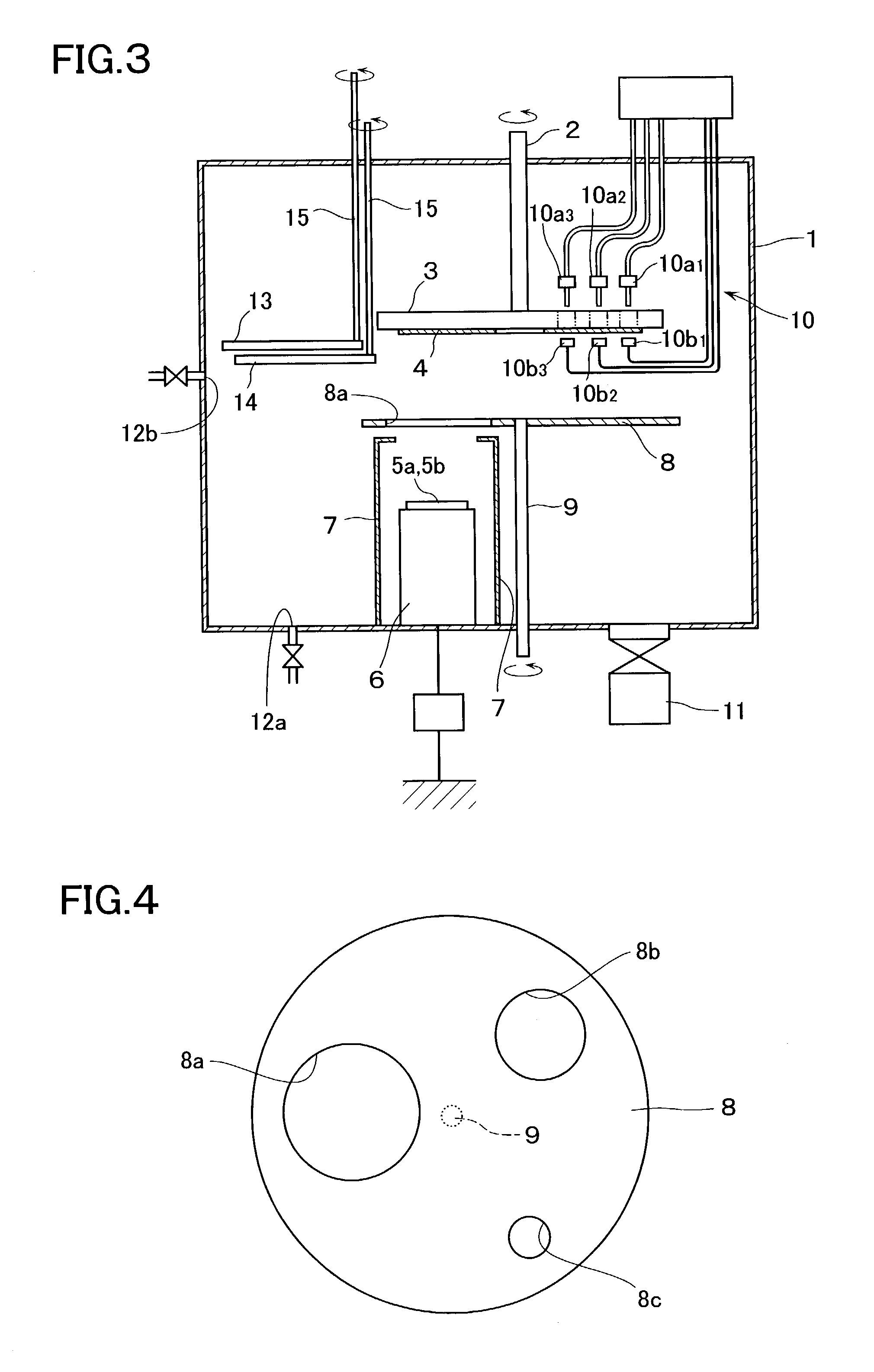
[0066]The sputtering apparatus in FIG. 3 was used to place an optically polished doughnut-shaped glass substrate having a diameter 200 mm on the substrate holder 3. Then, the inside of the chamber 1 was evacuated to pressure of 1×10⁻⁵ Pa or less. Then, 20 sccm of Ar gas was introduced through the gas introducing port 11, while 5 sccm of oxygen gas was introduced through the gas introducing port 12b. Thus, the inside of the chamber 1 was maintained at pressure of 0.5 Pa. The first and second film thickness correcting plates 13 and 14 were kept so as not to locate over the substrate. After confirming that none of the openings 8a, 8b and 8c in the shutter 8 were located over the sputtering cathode 6, the substrate holder 3 was rotated around the rotating shaft 2 at 1,500 rpm. Then, pulse DC electric power of 2-kW, which had been ready to prevent anomalous discharge, was applied to the sputtering cathode 6 to start discharging. The target material was Ti. The opening 8a in the shutter 8...

example 2

[0069]The sputtering apparatus in FIG. 3 was used to start film formation under the same conditions as in Example 1. TiO2 was formed at rate of 200 Å / min. Then, the shutter 8 was closed at first when the film thickness monitor 10 indicated a film thickness of 1,990 Å. The film thickness monitor was carried out upon one-point measurements, and measured the film thickness at plural points on the substrate 4 while moving in the radial direction of the substrate 4.

[0070]Then, the film formation was carried out at rate of 20 Å / min using the first film thickness correcting plate 13 having the opening 13a and the opening 8b in the shutter 8. The shutter 8 was closed again when the film thickness monitor 10 indicated a film thickness of 1,996 Å in total.

[0071]Next, the shutter 8 was closed again using the second film thickness correcting plate 14 having the opening 14a and the opening 8c in the shutter 8 when the film thickness monitor 10 indicated a thickness of 2,000 Å in total at film fo...

example 3

[0073]The third film thickness correcting plate 16, shown in FIG. 7 in a top view, was used instead of the first and second film thickness correcting plates 13 and 14 of the sputtering apparatus in FIG. 3. The third film thickness correcting plate 16 has such a structure that shutter splines 181 to 1814 were connected to microcylinders 171 to 1714 each by each, that each of the microcylinders 171 to 1714 might be stretchable using a signal cable 20 extending through the rotating shaft 19, and that the shape of the opening 16a might be arbitrarily variable by moving the splines 181 to 1814.

[0074]A film was formed by appropriately changing the shape of the opening 16a in the third film thickness correcting plate 16 under substantially the same conditions as in Example 2 except that the third film thickness correcting plate 16 was used instead of the first and second film thickness correcting plates 13 and 14. As a result, that the average film thickness was 2,000.0 Å and the distribut...


PUM

PropertyMeasurementUnit
pressureaaaaaaaaaa
pressureaaaaaaaaaa
thicknessaaaaaaaaaa

Abstract

The present invention provides an efficient thin film forming apparatus which is capable of correcting a film thickness so as to take care of a variation in distribution in the film thickness and to take care of the circumferential distribution of the film thickness, as well as a method for forming a thin film using this film forming apparatus. The method comprises the first step of first forming a thin film to a predetermined percentage out of thickness through an opening 8a in a shutter 8, the second step of then using a film thickness monitor 10 to measure the distribution of the thickness of the thin film formed in the first step, and the third step of reducing a film formation rate by an opening 8b in the shutter 8 between a substrate 4 and a sputtering cathode 6 as compared to that of the first step and correcting the thickness of the thin film by an opening 13a in the first film thickness correcting plate 13 between the substrate 4 and the sputtering cathode 6 corresponding to the distribution of the film thickness measured by the film thickness monitor 10 in the second step. Then, the second step is carried out again, during which the film thickness monitor 10 is used to measure the distribution of the thickness of the thin film formed in the third step. Further, the third and second steps are repeatedly carried out.

Description

BACKGROUND OF THE INVENTION[0001]1. Field of the Invention[0002]The present invention relates to an apparatus which forms a thin film on a substrate and a method for forming a thin film using the apparatus. For example, when a film is formed on a glass substrate using a sputtering apparatus and the like, on the occasion that sputtering grains deposit at desired positions on the substrate to form a thin film, such a thin film tends to be formed, so that the distribution of film thickness gives a peak in a portion of the substrate corresponding to a target center in the radial direction of the rotatable substrate in spite of rotation of the substrate intended to allow film formation conditions to be uniform. Furthermore, in the circumferential direction of the rotatable substrate, depending on the places where film formation is started and ended on the rotated substrate, such a distribution of film thickness tends to be obtained that these places constitute the start and end points of...

Claims


Application Information

Patent Timeline
Patent Type & Authority Patents(United States)
IPC IPC(8): C23C14/35C23C16/00C23C14/04H01L21/203C23C14/54
CPCC23C14/545C23C14/044H01L21/203
Inventor TANI, NORIAKISUZUKI, TOSHIHIROIKEDA, SATOSHIKAWAMURA, HIROAKIISHIBASHI, SATORUHANZAWA, KOUICHIMATSUMOTO, TAKAFUMI
Owner ULVAC INC
Why Eureka
Try Eureka