Control apparatus and method of electric rotating machine for vehicle

a technology of electric rotating machines and control apparatus, which is applied in the direction of electric generator control, engine starters, electric devices, etc., can solve the problems of inability to obtain charging voltage for vehicle-mounted batteries, inability to control the electric rotating machine, and increased internal combustion engine start-ups inevitably, so as to reduce the frequency of shock, prevent insufficient charge, and prevent frequent switchover of power generation modes

Inactive Publication Date: 2006-04-25
MITSUBISHI ELECTRIC CORP
View PDF6 Cites 10 Cited by
  • Summary
  • Abstract
  • Description
  • Claims
  • Application Information

AI Technical Summary

Benefits of technology

[0014]As a result, it is possible to prevent frequent switchover of the power generation mode even if the internal combustion engine is operated at a specific rotating speed. Furthermore, it is possible to prevent insufficient charge that occurs, when the power generation mode is switched over, and reduces frequent occurrence of shock due to change in engine speed of the internal combustion engine.

Problems solved by technology

In those vehicles, number of starts of the internal combustion engine increases inevitably.
Accordingly, in order to obtain these motor characteristics within a limited space, the generator characteristics are sacrificed and it is not possible to obtain charging voltage for the vehicle-mounted battery when the electric rotating machine rotates at a low speed.
Thus, the field current is interrupted and power generation is interrupted undesirably every time the power generation mode is switched over.
This makes the vehicle-mounted battery to loose its balance between charge and discharge resulting in lowering power source voltage.
Consequently, the switchover of the power generation mode is accompanied by a change in engine speed of the internal combustion engine, eventually resulting in occurrence of a shock.

Method used


Image

  • Control apparatus and method of electric rotating machine for vehicle
  • Control apparatus and method of electric rotating machine for vehicle
  • Control apparatus and method of electric rotating machine for vehicle

Examples


embodiment 1

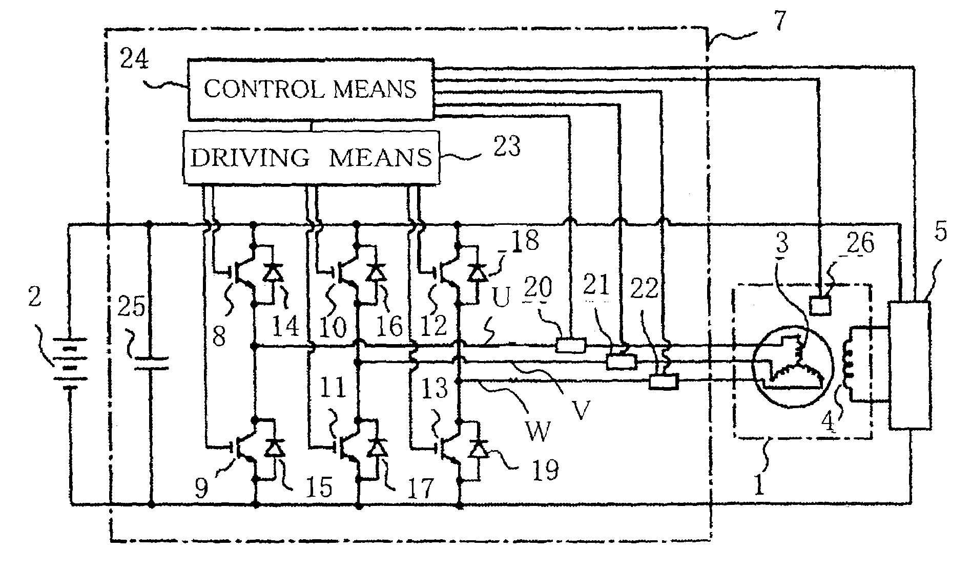
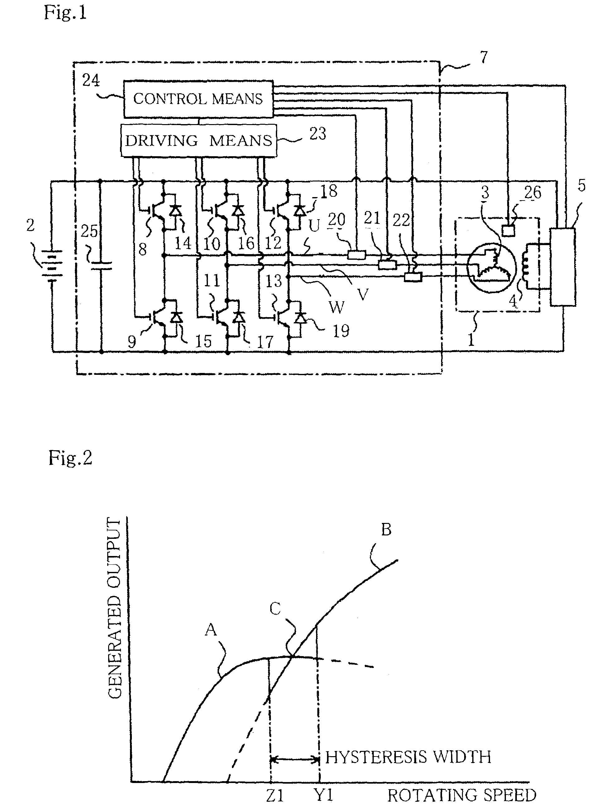
[0021]FIGS. 1 and 2 are drawings for explaining a control apparatus and a control method for controlling an electric rotating machine for vehicle according to Embodiment 1 of the present invention. FIG. 1 is a schematic circuit diagram of the electric rotating machine for vehicle and the control apparatus for controlling the electric rotating machine, and FIG. 2 is a characteristic diagram for explaining operation. Referring to FIG. 1, reference numeral 1 is an electric rotating machine that is connected to a vehicle-mounted internal combustion engine and functions as a starter motor for starting the internal combustion engine not shown as well as a charging generator for charging a vehicle-mounted battery 2. The electric rotating machine 1 includes a stator having, for example, a three-phase armature coil 3 and a rotor having a field coil 4. The field coil 4 is supplied with a field current from the battery 2 through a field current control means 5. When a power is generated, the f...

embodiment 2

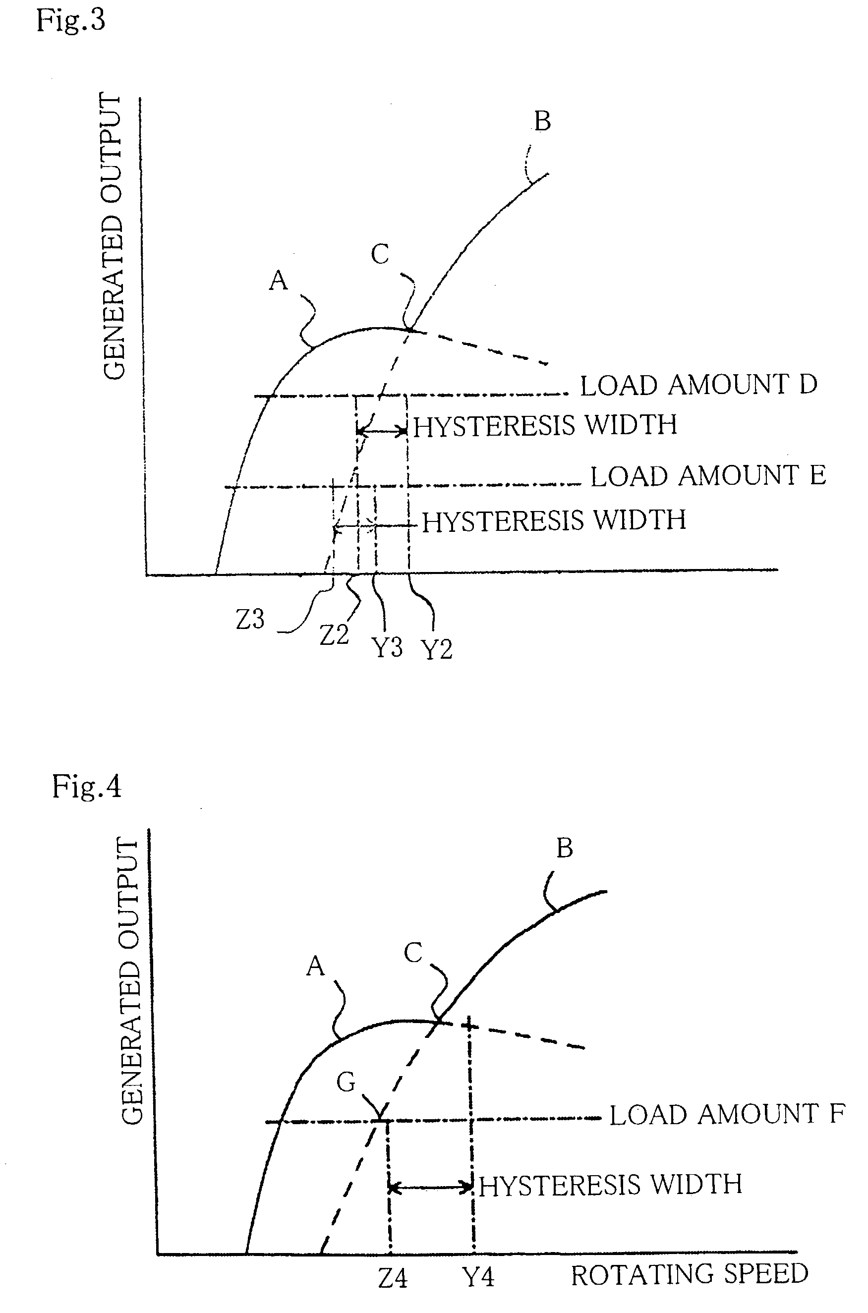
[0029]FIG. 3 is a characteristic diagram for explaining operation of a control apparatus and control method for controlling an electric rotating machine for vehicle according to Embodiment 2 of the invention. The control apparatus and control method for controlling an electric rotating machine for vehicle according to this embodiment differs from that in the foregoing Embodiment 1 in the aspect of conditions of switching the power generation mode carried out by the control means 24. In FIG. 3, lines D and E respectively indicate amounts of electric load on the electric rotating machine 1.

[0030]In the case where the electric load on the electric rotating machine 1 is a partial load and is in a state of the line D, the control means 24 detects an amount of the load by the current detecting means 20 to 22. When the rotating speed of the electric rotating machine 1 is increased, the power generation mode is switched from the inverter generation mode to the alternator generation mode at ...

embodiment 3

[0032]FIG. 4 is a characteristic diagram for explaining operation of a control apparatus for controlling an electric rotating machine for vehicle according to Embodiment 3 of the invention. The control apparatus for controlling an electric rotating machine for vehicle according to this embodiment differs from that in the foregoing Embodiment 1 or Embodiment 2 in the aspect of conditions of switching the power generation mode carried out by the control means 24. Referring now to FIG. 4, a line F indicates an amount of an electric load on the electric rotating machine 1, and a point G indicates an intersection of the electric load amount F and the output characteristic of the electric rotating machine 1 in the alternator generation mode.

[0033]In this embodiment, when the electric load on the electric rotating machine 1 is a partial load and is in a state of the line F in FIG. 4, the control means 24 detects an amount of the load by the current detecting means 20 to 22. When rotating s...


PUM


Abstract

A control apparatus and method for controlling an electric rotating machine for vehicle reduces shock at the time of switching power generation mode. The control apparatus include an electric rotating machine functioning as a starter motor and a charging generator 1, an inverter comprised of switching elements 14 to 19, a field current controller 5 for controlling an electric current of a field coil 4 of the electric rotating machine 1, and a controller 24 by which power is generated in an inverter generation mode in a low-speed rotation range and in an alternator generation mode in a high-speed rotation range. A hysteresis is established between a rotating speed in switching from the inverter generation mode to the alternator generation mode and a rotating speed in switching from the alternator generation mode to the inverter generation mode under the control of the controller 24.

Description

BACKGROUND OF THE INVENTION[0001]1. Field of the Invention[0002]The present invention relates to a control apparatus and a method for controlling an electric rotating machine for vehicle, in which the electric rotating machine acts as a starter motor when an internal combustion engine is started and acts as a generator after the internal combustion engine has started.[0003]2. Description of the Related Art[0004]It is a recent trend that a system, in which internal combustion engine stops upon stopping the vehicle (i.e., idle stop), has been increasingly adopted in vehicles in consideration of reduction in carbon dioxide emission and improvement in fuel consumption. In those vehicles, number of starts of the internal combustion engine increases inevitably. It is therefore preferable to adopt a combined starter motor / charging generator in which the internal combustion engine and the electric rotating machine are combined at all times and less noise is produced as compared with a conve...

Claims


Application Information

Patent Timeline
Patent Type & Authority Patents(United States)
IPC IPC(8): B60L1/00B60L9/18B60L50/16H02P9/30
CPCH02P9/30H02P9/305H02P1/52H02P27/04F02N11/04H02P9/04
Inventor KURIBAYASHI, MASARU
Owner MITSUBISHI ELECTRIC CORP
Why Eureka
Try Eureka