Full inspection of an object, such as a
semiconductor wafer, requires several separate very expensive machines.
Most imaging modes have difficulty detecting changes in the height of features.
Collection angles are also limited to the range of angles within the NA of the objective.
This objective pupil feature seriously limits the types of illumination and
Fourier filtering that are possible.
This
high angle illumination is not possible without a higher NA objective.
This seriously limits the number of resolvable points in the image and the achievable inspection speed.
Another problem with this technique is small amounts of scattered and reflected light from lens elements in this system have the ability to produce
noise at levels that compromise the sensitivity.
Introducing
laser illumination from inside this type of objective can cause a significant amount of scattered and reflected light from the multiple lens surfaces.
If the system uses a small spot for high sensitivity detection, the inspection speed tends to decrease dramatically.
If a larger spot size is used to increase inspection speed, the overall system sensitivity degrades.
This makes the combination of the double dark field mode and other imaging modes such as bright field and
laser directional dark field difficult.
First,
physical limitations tend to
restrict the angle at which light beams may be applied to the object, i.e. at either extremely deep or extremely shallow angles.
This angular limitation tends to impede a full examination of the object.
Secondly, these systems only employ one dark field mode each, which again tends to limit the types of defects which may be detected.
Any attempt to combine different dark field imaging systems would be severely inhibited due to physical
component placement restrictions and the inherent cost associated with multiple components.
The problem, however, is that no single mode provides these capabilities, nor is a combination of these modes physically realizable nor economically feasible.
Further, the use of multiple arrangements running over different machines negatively effects the scanning,
processing, and evaluating time for each specimen.
While these systems may have a similar appearance to the present invention, they simply do not have the capability to integrate multiple inspection modes.
This limited NA and
field size does not support high speed inspection with more than one dark field mode.
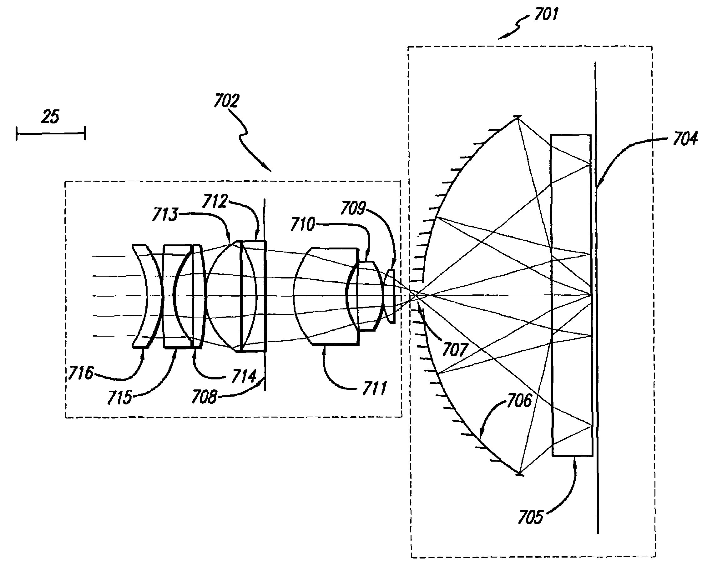
This is a 0.9 NA system with very tight manufacturing tolerances, primarily due to the broad-band requirements of the design.
Common problems with using several of these prior catadioptric optical systems for multiple imaging modes includes: these are complicated systems with tight manufacturing tolerances, they provide no illumination and imaging above 0.9 NA and a
field of view less than 1 mm, pupil planes that are not easily accessible, and limited imaging modes and associated illumination schemes.

