Method and circuit arrangement with adaptive overload protection for power switching devices

a power switching device and adaptive overload protection technology, applied in the direction of emergency protective arrangements for limiting excess voltage/current, electronic switching, pulse technique, etc., can solve the problems of affecting the drive circuit, limiting the reliability and non-destructive operation of such circuits, and conventional arrangement of power circuits using modem components experiencing a variety of errors, so as to reduce the thickness of the insulation layer, reduce the live surface, and increase the power density of the circuit arrangement

Inactive Publication Date: 2006-04-25
SEMIKRON ELECTRONICS GMBH & CO KG
View PDF14 Cites 28 Cited by
  • Summary
  • Abstract
  • Description
  • Claims
  • Application Information

AI Technical Summary

Benefits of technology

[0021]State of the art measures to increase the power density in circuit arrangements include using suitable parallel copper plates as conductor tracks, minimizing the live surfaces, minimizing the thickness of the insulation layer in case of closely adjacent plates of opposite poles, parallel-switching of parasitic inductivities and combining the homopolar tracks over short paths when the transmission line cross-section is large.
[0022]Recently, sensors for detecting and evaluating various parameters of power converter arrangements in real time have gained popularity. Current and temperature sensors have become routine components in circuit arrangements requiring high performance or reliability. The instantaneous signals from such sensors are generally compared with threshold values. When the measured signals exceed the threshold values, the entire system is shut down to prevent damage or destruction.

Problems solved by technology

However, ever increasing power density demands strain the reliability and non-destructive operation of such circuits.
Conventional arrangements of power circuits using modem components experience a variety of errors.
The errors experienced, while conventional in nature, may adversely impact the drive circuit.
The impact of such errors may lead to false gating, which in turn can cause the circuit to fail, or introduce other serious negative effects in the functional operation of the circuit.
Power circuits with very high component density tend to exhibit particular drawbacks when the main power and the drive circuits are in close proximity to each other.
Such circuits generally have a complex configuration which is sensitive to the magnetic field generated by the main power supply.
The functional safety of these circuits is particularly susceptible to errors in high-speed power switching applications such as circuit breakers which have high di / dt values.
Optimal circuit performance is difficult to achieve because the circuit design can compensate for only a portion of all the interference sources.
Sources of interference occurring in practical operation can create fluctuations of individual parameters of circuit operation.
Realistically, it is difficult to design a circuit that compensates for all of the individual parameters of circuit operation.
However, such reserves are not objectively useful for circuit functionality, and still have a negative effect on total power dissipation.
The sources and range of potential interference are very large.
Variable path lengths of parallel circuits consisting of divided DC circuits is another source of interference which leads to unwanted fluctuations in power switch drives.
Cooling systems used in power switches are another potential source of negative effects on the tolerance of the overall system.
As a practical matter, the cooling provided to the DCB ceramic substrate by a heat sink is unevenly distributed in temperature and location.
Periodic changes in components with the accompanying individual changes in static values leads to the problem of exceeding overall operating range parameters.

Method used


Image

  • Method and circuit arrangement with adaptive overload protection for power switching devices
  • Method and circuit arrangement with adaptive overload protection for power switching devices
  • Method and circuit arrangement with adaptive overload protection for power switching devices

Examples


Embodiment Construction

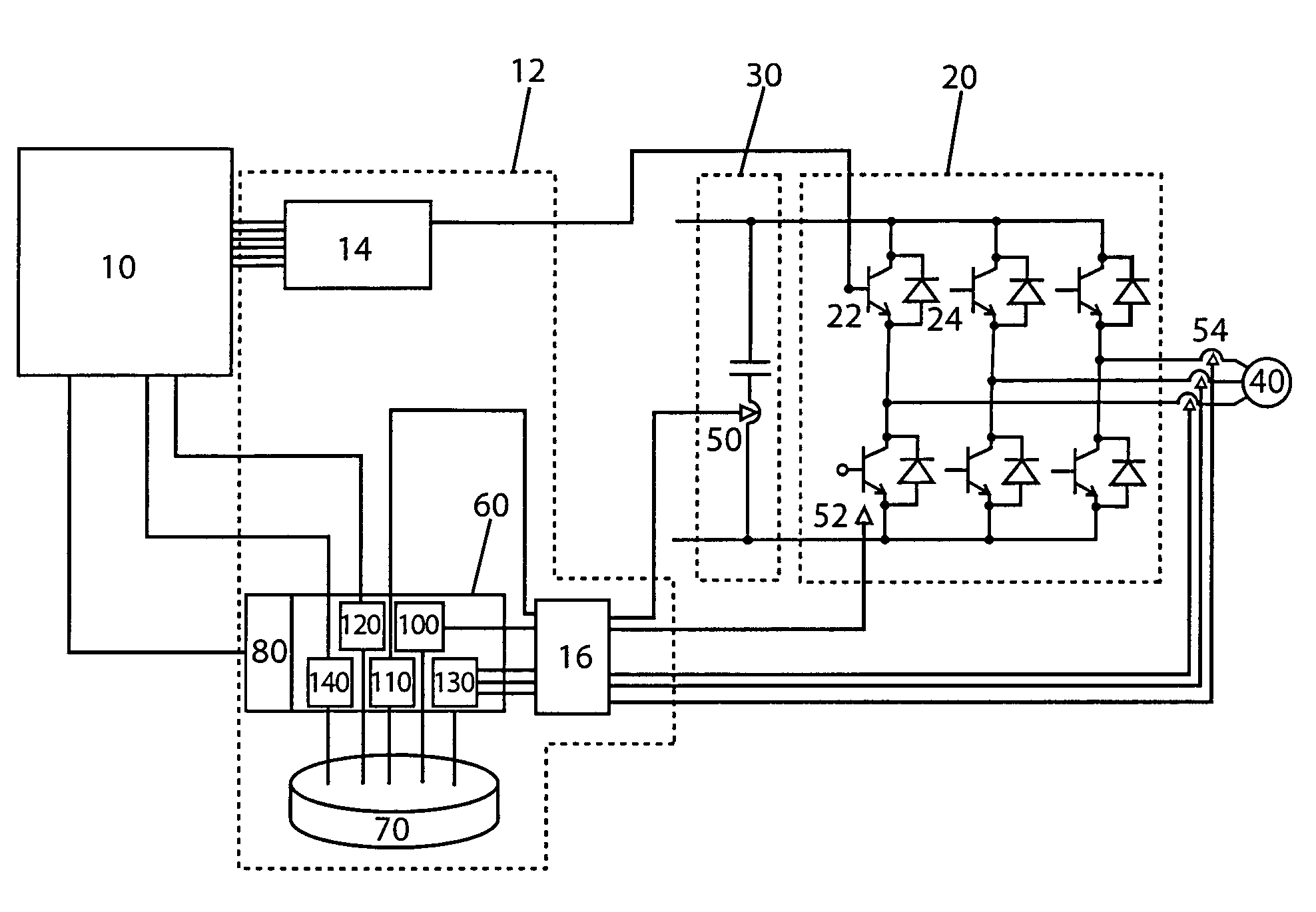
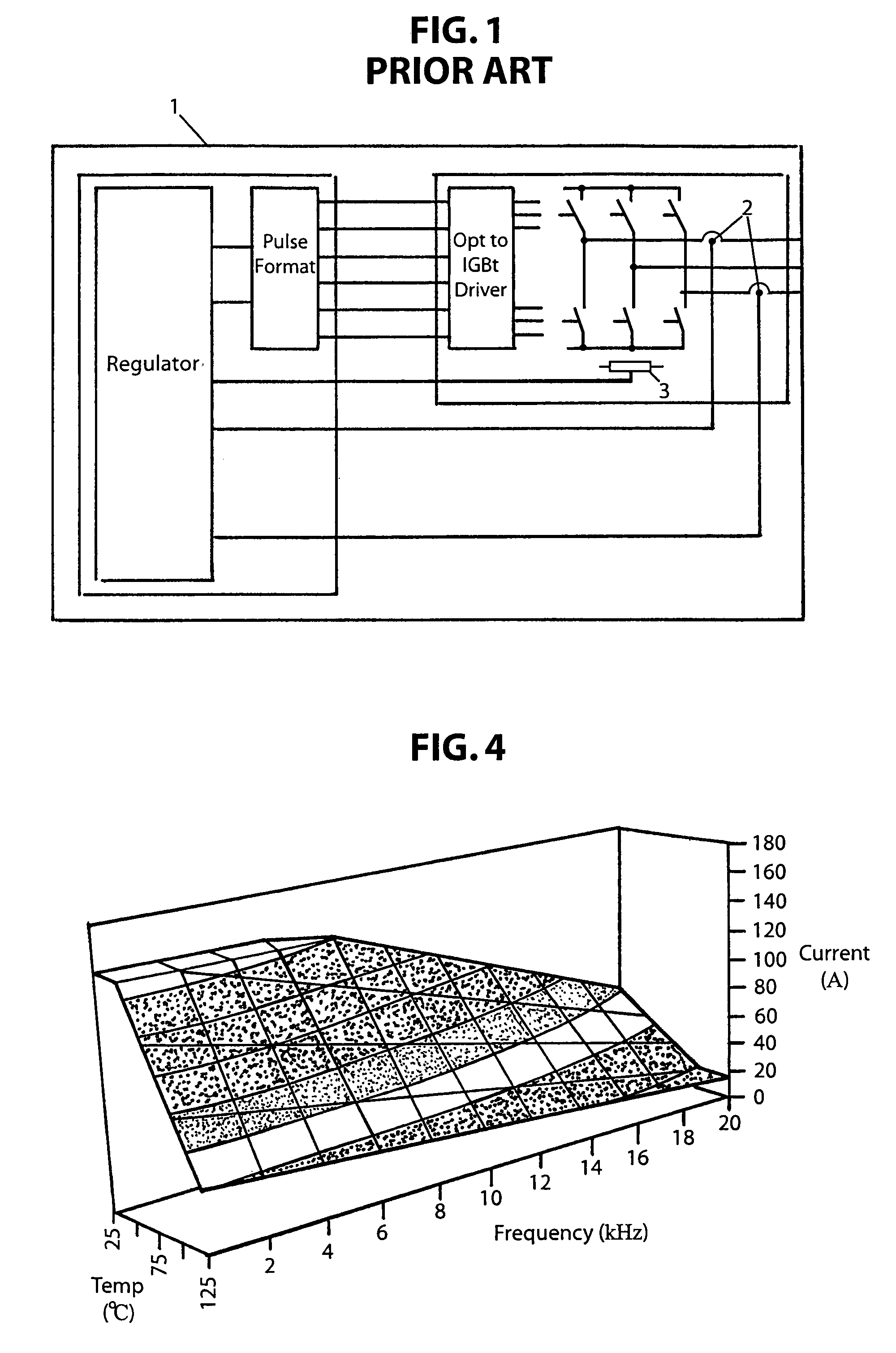
[0049]Referring to FIG. 1, a conventional power converter is shown according to the modem state of the art in circuit technology. Converter 1 has output currents monitored by current sensors 2, and temperatures monitored by sensor mounted on a heat sink 3. The circuit provides current overload protection by comparing the instantaneous value of the current signal with a threshold value which lies outside the normal operating value range. When the threshold value is exceeded, the total system, i.e. the circuit arrangement, is shut off.

[0050]In such systems, threshold values are determined on the basis of thermal measurements made during circuit development and testing phases. It is also during the circuit development phase that forecasts for permitted loads are made for a range of certain heat-sink temperatures. These forecasts form the basis of the threshold values of all subsequently established arrangements. A static thermal model of the circuit arrangement for the specified compon...


PUM


Abstract

Dynamic thresholds for power circuit switch operation are calculated in real-time using instantaneous operating parameter measurements. The dynamic thresholds are self-adapting and are used to provide shutdown criteria independent of switch control systems. A characteristics field containing information related to operation parameters is used to make overload evaluations in real-time. These dynamic overload evaluations allow complete protection against thermal overload for entire power circuits in addition to power components. Reserve load capacity can also be determined based on well known component characteristics, which permits the power circuit to be driven at optimal efficiency. The power circuit output profile can also be modified in response to dynamic overload evaluation, thus preventing overload shutdown or damage to components, while operating at optimal efficiency.

Description

[0001]This application is a continuation-in-part of U.S. Ser. No. 09 / 320,871, filed May 27, 1999.BACKGROUND OF THE INVENTION[0002]The invention relates to a circuit arrangement for current converters. More particularly, the invention relates to a method and circuit arrangement with adaptive overload protection for use with power switching devices, including Isolated Gate Bi-polar Transistor (IGBT) or Metal Oxide Semiconductor Field Effect Transistor (MOSFET) switches including associated free-running diodes.[0003]Several types of circuits with overload protection for power semiconductor components are known. However, ever increasing power density demands strain the reliability and non-destructive operation of such circuits.[0004]Conventional arrangements of power circuits using modem components experience a variety of errors. Such circuits include transistor switches using IGBT and MOSFET technology, and modem free-running diodes with soft-recovery behavior as shown in DE 4421529A1....

Claims


Application Information

Patent Timeline
Patent Type & Authority Patents(United States)
IPC IPC(8): H02H7/09H02M1/00H03K17/08H03K17/082
CPCH03K17/0828H03K17/0822H02M1/32H03K2017/0806H02M1/327
Inventor SCHIMANEK, ERNSTBILLMANN, MARKUS
Owner SEMIKRON ELECTRONICS GMBH & CO KG
Why Eureka
Try Eureka