Device to protect an active implantable medical device feedthrough capacitor from stray laser weld strikes, and related manufacturing process

a technology of active implantable medical devices and feedthrough capacitors, which is applied in the direction of feed-through capacitors, variable capacitors, therapy, etc., can solve the problems of premature failure of aimd, difficult electric field relaxation, and dangerous or even life-threatening for pacemaker dependent patients

Inactive Publication Date: 2006-04-25
WILSON GREATBATCH LTD
View PDF44 Cites 95 Cited by
  • Summary
  • Abstract
  • Description
  • Claims
  • Application Information

AI Technical Summary

Problems solved by technology

However, the lead wires can also undesirably act as an antenna and thus tend to collect stray EMI signals for transmission into the interior of the AIMD.
All of these situations can be dangerous or even life threatening for a pacemaker dependent patient.
Degradation of insulation resistance or electrical failure of the feedthrough capacitor and / or the related feedthrough terminal assembly would lead to premature failure of the AIMD.
This makes it very difficult for the electric fields to relax without creating microcolumb discharges, streamers or high voltage arcs.
Making lead attachments to circuits inside a pacemaker can cause heat, splatter or debris from the related coupling operations, i.e., welding, thermal or ultrasonic bonding, soldering, brazing, etc., to land on the capacitor's conformal coating.
This heat, splatter or debris can cause localized melting or disruption of the conformal coating or embedding of metallic particles, all of which can lead to high voltage breakdown of the device.
This can lead to immediate or delayed failure of the AIMD, which, as mentioned above, could be life threatening to a patient.
Too thick of a conformal coating could lead to cracking of the dielectric in the feedthrough capacitor which can also cause reliability problems.

Method used


Image

  • Device to protect an active implantable medical device feedthrough capacitor from stray laser weld strikes, and related manufacturing process
  • Device to protect an active implantable medical device feedthrough capacitor from stray laser weld strikes, and related manufacturing process
  • Device to protect an active implantable medical device feedthrough capacitor from stray laser weld strikes, and related manufacturing process

Examples


Embodiment Construction

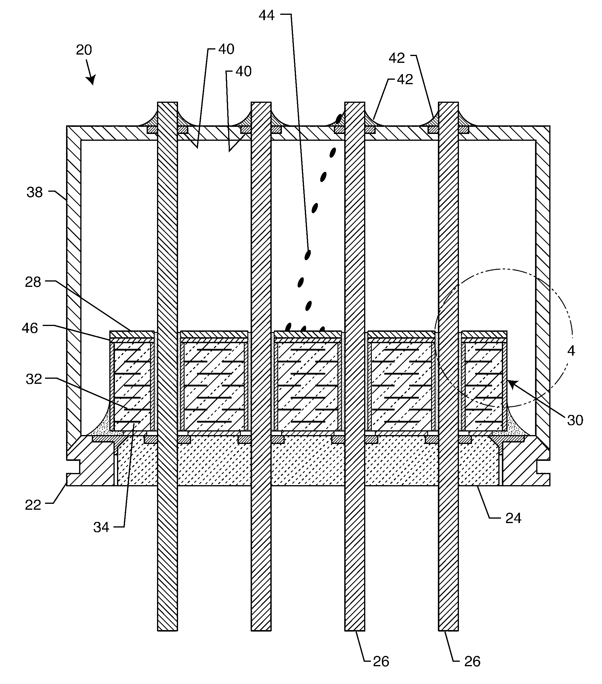
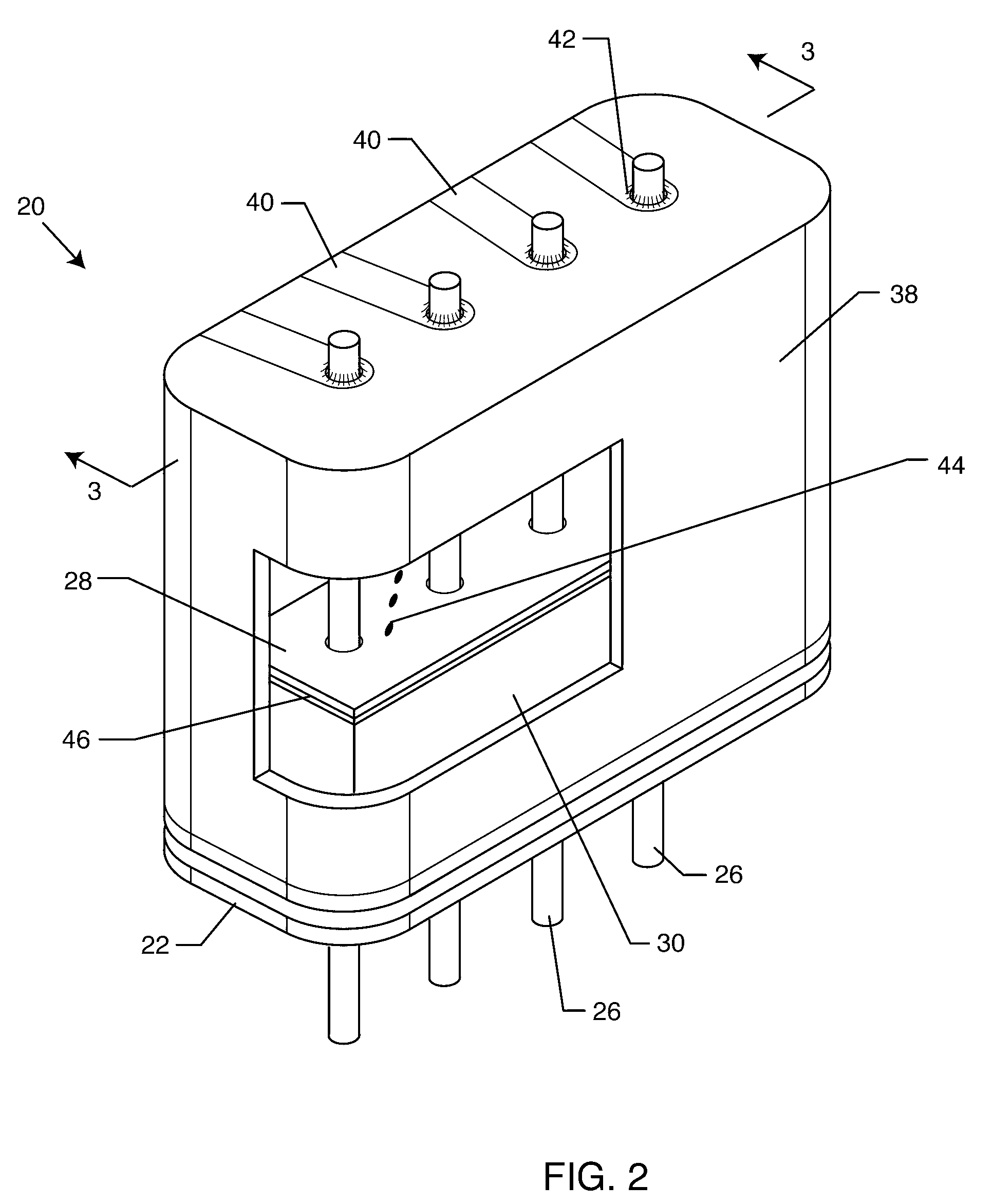
[0023]The present invention resides in a thin substrate or insulative shield co-bonded to the top surface of a feedthrough capacitor in a feedthrough filter assembly. The insulative shield provides protection from heat, splatter or debris from lead attachment techniques. The insulative shield is co-bonded using the capacitor's own conformal coating material. In this way, the high voltage electric fields contained within the feedthrough capacitor can still make a transition to a material having a low dielectric constant (K), before contacting air. In fact, the insulative shield has a much lower dielectric constant than the dielectric in the feedthrough capacitor, which also helps to relax the high voltage fields.

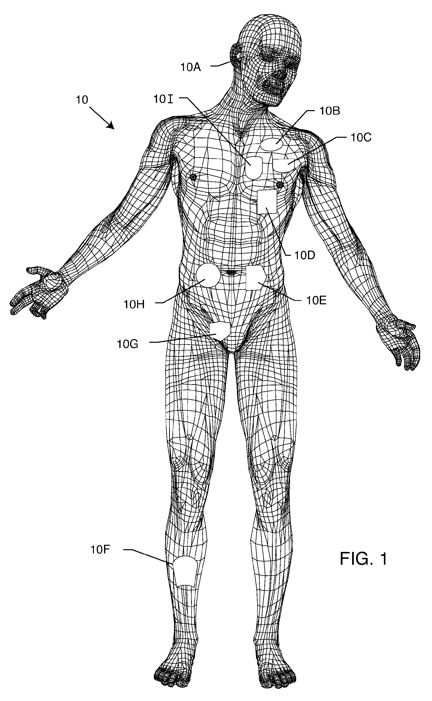
[0024]FIG. 1 is a wire formed diagram of a generic human body showing a number of types and locations of active implantable medical devices 10. 10A is a family of hearing devices which can include the group of cochlear implants, piezeoelectric sound bridge transducers and the...


PUM

PropertyMeasurementUnit
dielectric constantaaaaaaaaaa

Abstract

An insulative shield is co-bonded to the top of a ceramic capacitor in a feedthrough terminal assembly on an active implantable medical device. The insulative shield is a thin substrate that provides protection against damage and degradation of the feedthrough capacitor and / or its conformal coating from heat, splatter or debris resulting from the electromechanical connection of components during construction of the assembly. Laser welding, thermal or ultrasonic bonding, soldering, brazing or related lead attachment techniques can create such heat, splatter or debris. In a preferred embodiment, the insulative shield is co-bonded using the capacitor's own conformal coating.

Description

BACKGROUND OF THE INVENTION[0001]This invention relates generally to electromagnetic interference (EMI) feedthrough terminal assemblies, and related methods of construction, designed to decouple and shield undesirable electromagnetic interference signals from associated active implantable medical devices (AIMDs), such as cardiac pacemakers, implantable defibrillators, cochlear implants, neurostimulators, active drug pumps, and the like. More particularly, the present invention relates to an improved EMI feedthrough terminal assembly that includes an insulating shield to prevent damage or degradation to a feedthrough capacitor or its adjunct conformal coating from lead assembly methods, including laser welding, thermal or ultrasonic bonding or the like.[0002]Feedthrough terminal assemblies are generally well known in the art for conducting electrical signals through the housing or case of an electronic instrument. For example, in AIMDs, the feedthrough terminal assembly comprises one...

Claims


Application Information

Patent Timeline
Patent Type & Authority Patents(United States)
IPC IPC(8): H01G4/35
CPCA61N1/3754H01G4/35H01G2/103A61N1/3718Y10T29/43
Inventor BRENDEL, RICHARD L.
Owner WILSON GREATBATCH LTD
Why Eureka
Try Eureka