Boiler and burner apparatus

a burner and burner technology, applied in lighting and heating equipment, fire-box steam boilers, water heaters, etc., can solve the problems of increasing the difficulty, and related costs of casting process, increasing the difficulty of boiling, and reducing the possibility of boiling in the boiler fluid. , the effect of reducing the sensibility to boiling

Inactive Publication Date: 2006-05-02
MESTEK
View PDF5 Cites 21 Cited by
  • Summary
  • Abstract
  • Description
  • Claims
  • Application Information

AI Technical Summary

Benefits of technology

[0013]It is another object of the present invention to provide a down-fired boiler and burner apparatus that reduces the sensibility to boiling as well as increasing the efficiency of the burner assembly.
[0014]It is another object of the present invention to provide a down-fired boiler that reduces the possibility of boiling in the boiler fluid.
[0015]It is another object of the present invention to provide a down-fired boiler and burner apparatus that increases the circulation and velocity of boiler fluid.
[0016]It is another object of the present invention to provide a down-fired boiler and burner apparatus that produces a substantially silent ignition of the fuel mixture.

Problems solved by technology

As will be appreciated, boiling of the boiler fluid causes a substantial, and frequently rapid, expansion of the boiler fluid volume, which may precipitate possible catastrophic damage to the system as a whole.
In below-fired boilers, the burner assembly is typically located adjacent the bottom of the boiler, thereby causing rapid mixing and circulation of the boiler fluid due to buoyant convection in the total liquid volume.
The sheer number and configuration of the inner baffles increase the difficulty, and related costs, of the casting process when manufacturing typical cast iron boilers.
As known to those of skill in the art, localized areas of low or non-circulating boiler fluid creates an environment that may promote undesirable boiling.
As will be appreciated, the ignition of pockets of fuel located some distance away from the burner element causes a rough and oftentimes noisy ignition that, over time, may cause damage to the burner element as well as being audibly disconcerting.

Method used


Image

  • Boiler and burner apparatus
  • Boiler and burner apparatus
  • Boiler and burner apparatus

Examples


Embodiment Construction

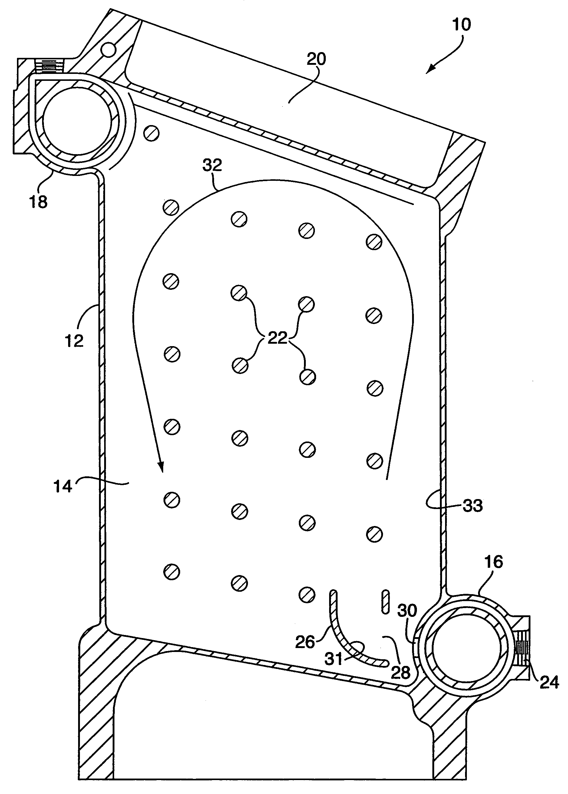
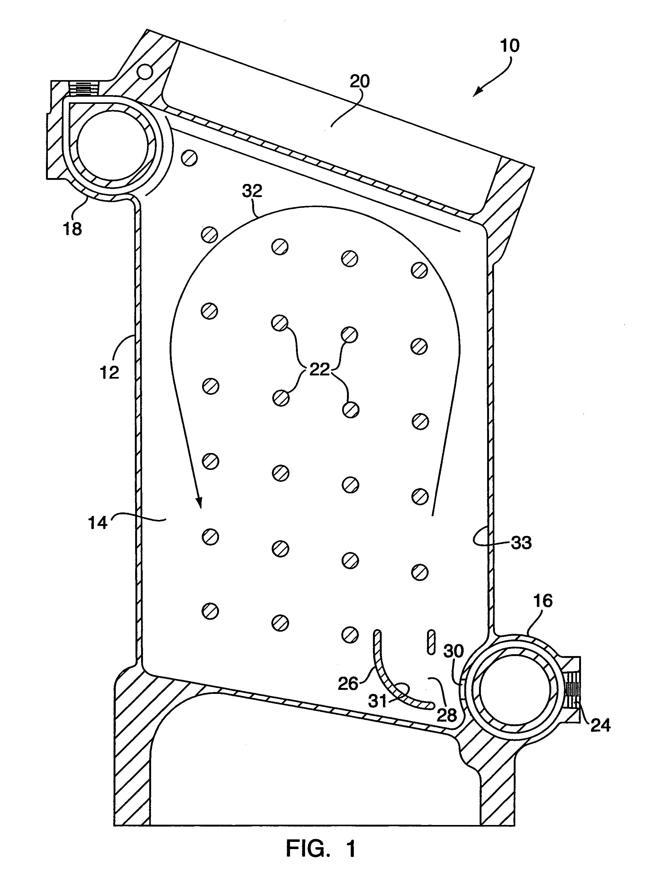
[0022]FIG. 1 illustrates a cross-sectional view of a down-fired boiler 10, in accordance with one embodiment of the present invention. As shown in FIG. 1, the boiler 10 includes a boiling housing 12 defining an inner boiler chamber 14. A boiler fluid inlet manifold 16 and a boiler fluid outlet manifold 18 are also shown in FIG. 1. A presently non-illustrated burner assembly is disposed adjacent the upper portion 20 of the boiler 10, and will be described in more detail later.

[0023]It will be readily appreciated that the boiler fluid most commonly utilized is water, although the present invention is not limited in this regard as alternative fluids may be utilized without departing from the broader aspects of the present invention.

[0024]Returning to FIG. 1, the inner volume of the boiler chamber 14 includes a plurality of structural stays 22 that are spaced throughout the inner volume of the boiler chamber 14. The stays 22 provide structural support to the boiler 10 when the boiler ch...


PUM


Abstract

A boiler apparatus includes a housing defining an interior boiler chamber and a burner element arranged to be in thermal communication with the boiler chamber. An ignition device is provided for instigating combustion of an inlet gas stream, and is arranged adjacent one edge of the burner element. A gas restricting device is utilized for restricting contact between the burner element and the inlet gas stream such that the inlet gas stream is initially incident upon the one edge of the burner element, thereby forcing the inlet gas stream to propagate across the burner element from the one edge.

Description

CROSS REFERENCE TO RELATED APPLICATIONS[0001]This application claims the benefit of U.S. Provisional Application Ser. No. 60 / 549,573, filed on Mar. 2, 2004, herein incorporated by reference in its entirety.FIELD OF THE INVENTION[0002]This invention relates in general to a boiler and burner apparatus, and deals more particularly with a down-fired boiler and burner apparatus that reduces the sensibility to boiling as well as increasing the efficiency of the burner assembly.BACKGROUND OF THE INVENTION[0003]In known cast iron boilers, typically utilized in residential or commercial settings to provide heated water for heating purposes or the like, the inhibition of a boiling action in the boiler fluid is paramount. As will be appreciated, boiling of the boiler fluid causes a substantial, and frequently rapid, expansion of the boiler fluid volume, which may precipitate possible catastrophic damage to the system as a whole. Thus, differing boiler configurations have been employed to preve...

Claims


Application Information

Patent Timeline
Patent Type & Authority Patents(United States)
IPC IPC(8): F22B13/02F22B23/06F24H1/22
CPCF22B23/06
Inventor COHEN, KENNETH W.
Owner MESTEK
Why Eureka
Try Eureka