Bi-directional power electronics circuit for electromechanical valve actuator of an internal combustion engine

a power electronics circuit and electromechanical actuator technology, applied in non-mechanical valves, electrical control, instruments, etc., can solve the problems of significant number of devices, significant added cost of an electromechanically actuated valve engine, and recognition of disadvantages, so as to reduce the number of devices and wires, reduce complexity, and improve the effect of cos

Active Publication Date: 2006-05-02
FORD GLOBAL TECH LLC
View PDF7 Cites 16 Cited by
  • Summary
  • Abstract
  • Description
  • Claims
  • Application Information

AI Technical Summary

Benefits of technology

[0012]In this way, it is possible to obtain bi-directional current control while still offering a reduction in device count and wire count. Thus, it may be possible to provide improved cost, reduced complexity, and reduced packaging space.

Problems solved by technology

However, the inventors herein have recognized a disadvantage when trying to use such converter designs to control electromechanically actuated valves of a cylinder in an internal combustion engine.
This creates a significant added cost for an engine with electromechanically actuated valves, even if not all valves are electrically powered.
Further, not only would the above converter approaches require significant numbers of devices, but would also increase wiring and harness costs, since two wires are required per actuator coil.
However, such a converter may not provide such operation, and therefore may lose the advantage of having permanent magnet enhancements.
Further, such a converter may still require 4 power devices (2 switches and 2 diodes) per electromagnet.

Method used


Image

  • Bi-directional power electronics circuit for electromechanical valve actuator of an internal combustion engine
  • Bi-directional power electronics circuit for electromechanical valve actuator of an internal combustion engine
  • Bi-directional power electronics circuit for electromechanical valve actuator of an internal combustion engine

Examples


Embodiment Construction

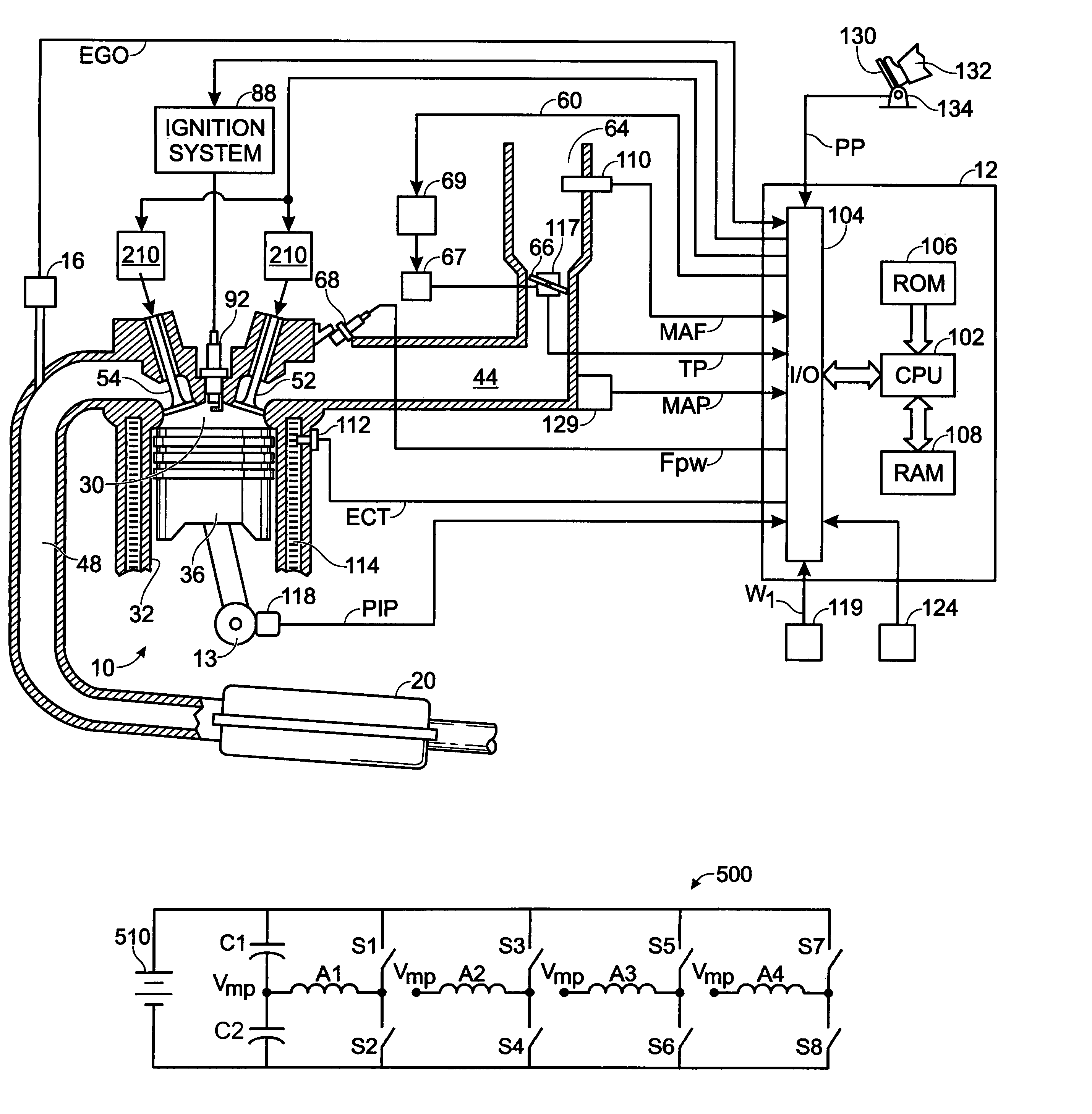
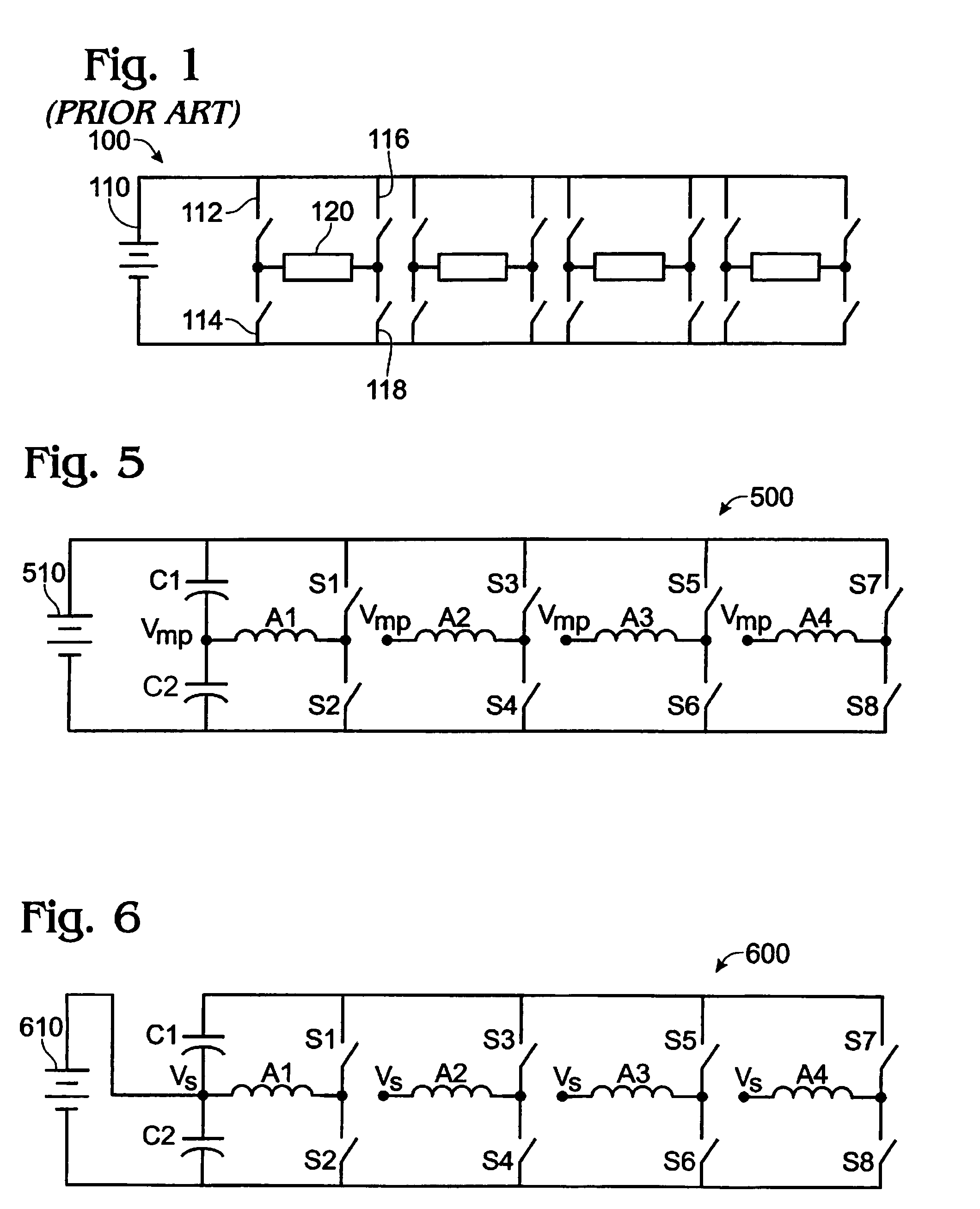
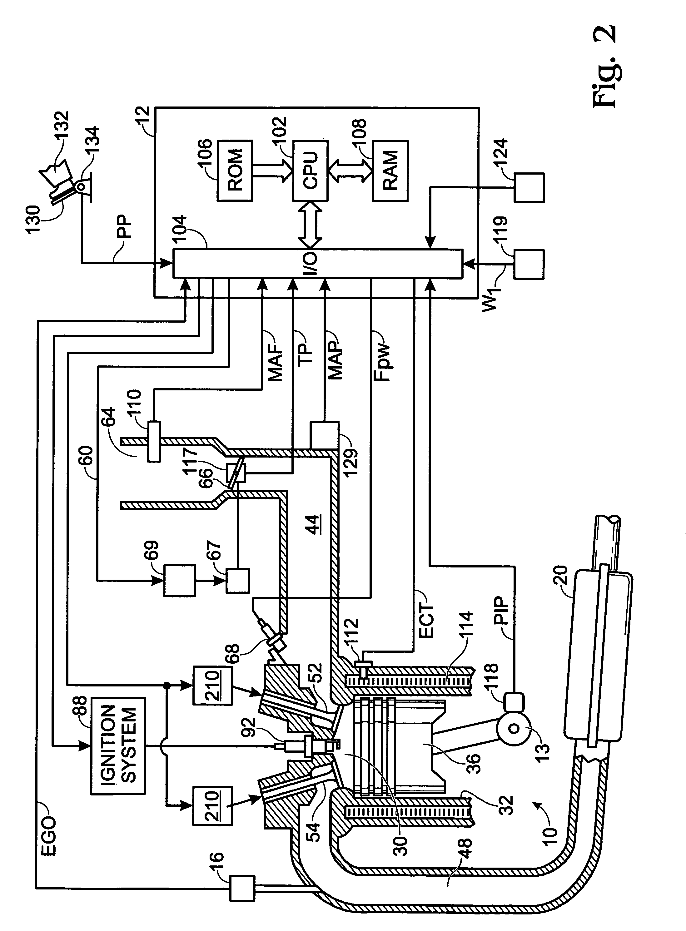
[0029]This disclosure outlines a converter topology form that can provide advantageous operation, especially when used with permanent magnet enhanced Electro-magnetic Valve Actuation (EVA) solenoid drivers of an internal combustion engine, as shown by FIGS. 2–4. This improved topology may result in a lower cost and lower component requirements, while maintaining desired functionality.

[0030]Referring to FIG. 2, internal combustion engine 10 is shown. Engine 10 is an engine of a passenger vehicle or truck driven on roads by drivers. Engine 10 can be coupled to a torque converter via crankshaft 13. The torque converter can also be coupled to transmission via a turbine shaft. The torque converter has a bypass clutch which can be engaged, disengaged, or partially engaged. When the clutch is either disengaged or partially engaged, the torque converter is said to be in an unlocked state. The turbine shaft is also known as transmission input shaft. The transmission comprises an electronical...


PUM

PropertyMeasurementUnit
electrical energyaaaaaaaaaa
voltageaaaaaaaaaa
charge balanceaaaaaaaaaa

Abstract

A bi-directional dual coil half bridge converter adapted to be coupled to a dual coil actuator of a cylinder valve in an internal combustion engine is described. In one example, the converter has a first and second capacitor and a voltage source, where the converter is actuated via switches to individually energizing coils in said dual coil actuator. A voltage regulator is also shown for maintaining midpoint voltage during unequal loading of different actuator coils in the converter.

Description

FIELD[0001]The field of the disclosure relates to power electronics for electromechanical actuators coupled to cylinder valves of an internal combustion engine, and more particularly for a dual coil valve actuator.BACKGROUND AND SUMMARY[0002]In multi-phase electronic converter applications, a number of bridge driver circuits (full or half) can be cascaded together while sharing a common power supply 110. A full bridge converter 100 is shown in FIG. 1 with four actuators (120) cascaded together. In this design, each load element 120 (actuator) is independently controlled by modulating the conduction of the appropriate power devices, in one of the three voltage operating modes (positive voltage, negative voltage, free-wheeling mode) by actuating switches 112 and 118, 114 and 116, 112 and 116 or 114 and 118, respectively. Note also that a half-bridge configuration can also be used for applications that do not require bi-directional current flow (where the power switches (114 and 116) a...

Claims


Application Information

Patent Timeline
Patent Type & Authority Patents(United States)
IPC IPC(8): F01L9/04F01L9/20F02D41/20H01F7/16H01F7/18H02M3/24H02M5/42H02M7/44H02M7/68
CPCF01L9/04H01F7/1816F02D41/20F01L2009/0426F01L2009/0436F01L2009/0469F01L2103/01F01L2800/13H01F2007/1822F02D2041/001F02D2041/2079H01F7/1638H01F7/1811H01F2007/1692F01L2303/01F01L2009/2126F01L2009/2136F01L2009/2169F01L9/20
Inventor DEGNER, MICHAELGRABOWSKI, JOHN
Owner FORD GLOBAL TECH LLC
Why Eureka
Try Eureka