
Crankcase heater mounting for a compressor

Inactive Publication Date: 2006-05-02
BRISTOL COMPRESSORS INT
View PDF13 Cites 8 Cited by
  • Summary
  • Abstract
  • Description
  • Claims
  • Application Information

AI Technical Summary

Benefits of technology

[0015]Oil sump fluid occupies at least a preselected minimum volume within the oil sump, such minimum volume being occupied when the oil sump fluid does-not contain any refrigerant during normal operation of the compressor. When the oil occupies the preselected minimum volume within the oil sump, the oil sump fluid rises to a preselected minimum height in the oil sump. The drainage of condensed refrigerant into the oil sump increases the volume of the oil sump fluid above its minimum volume. The presence of any liquid refrigerant within the sump increases the level of the oil sump fluid above its minimum height during normal operation of the compressor.
[0016]A heater well, with an outer surface and an inner surface, is located within a substantially planar portion in the lower section of the housing. The inner surface of the heater well faces the interior of the housing, while a portion the outer surface of the heater well forms a chamber having an opening. A substantial-portion of the inner surface of the heater well is in contact with the oil sump fluid at the preselected minimum oil sump fluid level. At higher levels of oil sump fluid, the entire inner surface of the heater well is in contact with the oil sump fluid. The chamber is designed to receive a heater assembly, such heater assemblies being well known in the art. The geometry of the housing, particularly the location and geometry of the substantially planar portion in the lower section of the housing and the location of the heater well serves to diminish the inherent property of the shell to transmit objectionable noise and vibrations at objectionable frequencies.
[0017]It is important, during both start-up and normal operation of the compressor to keep any refrigerant within the compressor housing in a vapor state and out of the oil sump. Since the refrigerant vaporizes at a lower temperature than the oil, heating the oil sump fluid above the evaporation temperature of the refrigerant serves to vaporize the refrigerant without vaporizing the oil. As the refrigerant is vaporized, it increases the partial pressure of the refrigerant within the compressor. The higher refrigerant vapor pressure within the compressor serves to prevent further condensation of the refrigerant vapor in the compressor housing. Since the interior of the heater well is substantially immersed in the oil sump fluid, even at low oil sump fluid levels, the heat generated from the heater unit located in the heater well is efficiently transferred from the heater assembly into the oil sump fluid. This transmission of heat directly from the heater unit into the oil sump fluid within the oil sump efficiently heats the oil sump fluid, driving any refrigerant located in the oil sump out of the oil sump fluid.
[0018]An advantage of this invention is a reduction in the amount of noise and vibration generated by a hermetic compressor during normal operation resulting from the position of the heater well within a substantially planar section of the housing.
[0019]Another advantage of this invention is efficient heating of the oil sump fluid in the lower section of a hermetic compressor by having the inner surface of a heater well substantially submerged in the oil sump fluid even at minimum oil sump fluid levels.
[0020]Another advantage of this invention is to provide efficient heating of the oil sump fluid in the lower section of a hermetic compressor by having the inner surface of a heater well completely submerged in the oil sump fluid at high oil sump fluid levels.

Problems solved by technology

However, if the heater wall were mounted on the vertical sidewall of the housing, the amount of sound and vibration generated during operation of the compressor would be increased.

Method used


Image

  • Crankcase heater mounting for a compressor
  • Crankcase heater mounting for a compressor
  • Crankcase heater mounting for a compressor

Examples


Embodiment Construction

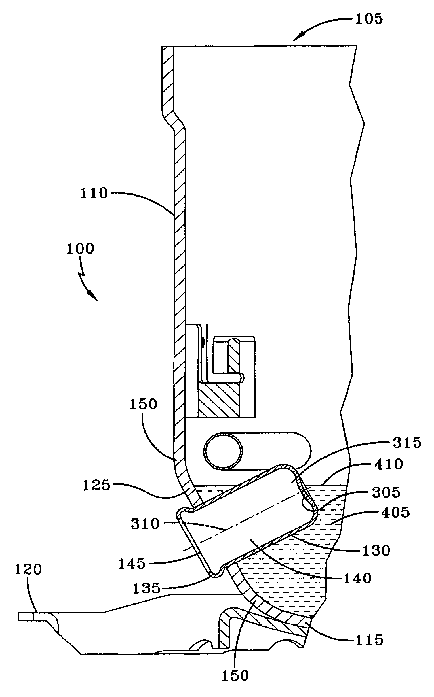
[0028]The compressor crankcase shell or housing of the present invention preferably has a generally cylindrical shape, and is dimensioned to enclose a compressing device, electric motor, and any corresponding auxiliary components such as a discharge muffler, suction line, motor cap or suction plenum, and the like. A typical compressor having utility for the present invention is shown in U.S. Pat. No. 4,995,791, the disclosure of which is incorporated herein by reference.

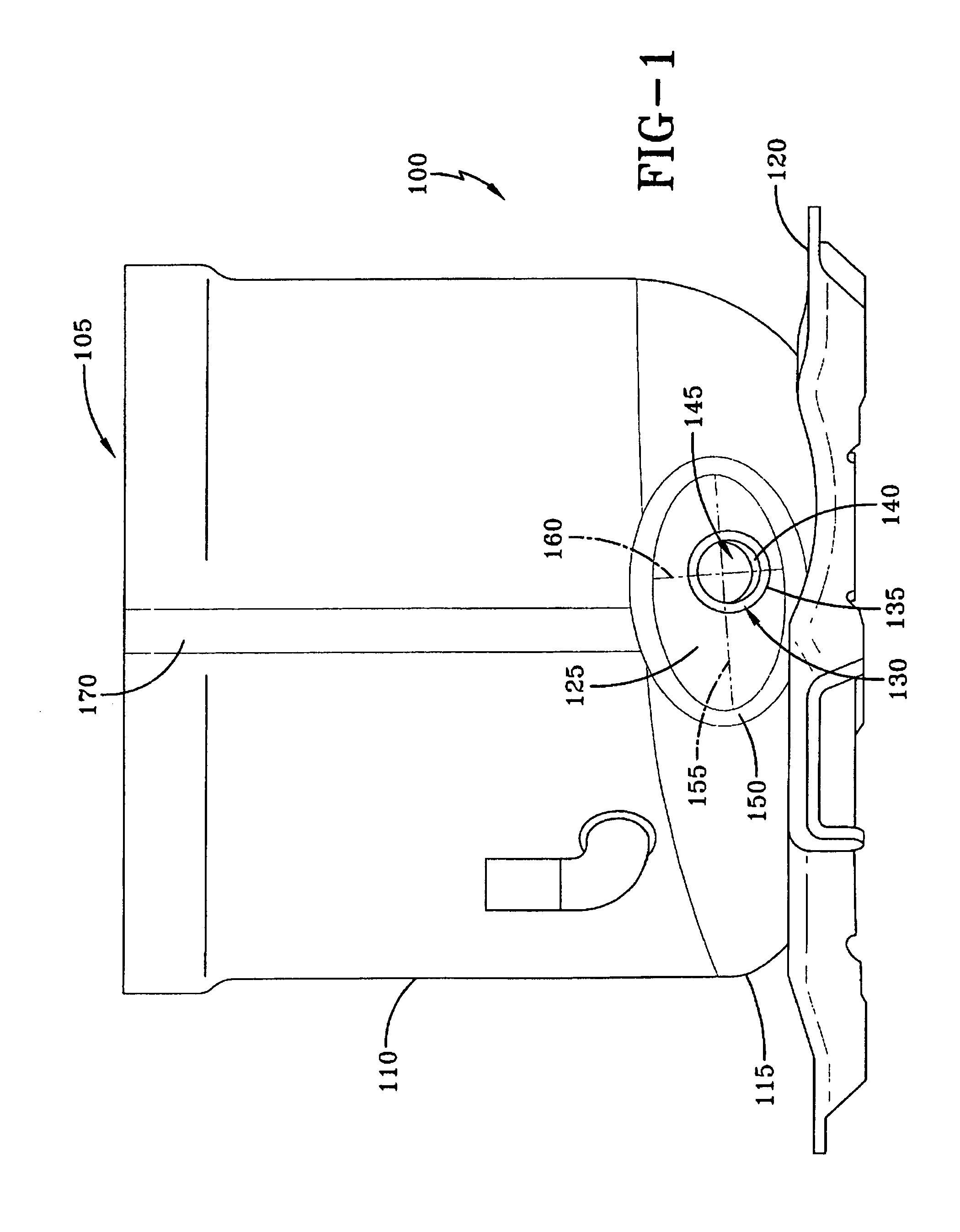
[0029]Referring now to FIG. 1, the hermetic compressor of the present invention includes two sections, an upper section 165 (shown in FIG. 5) and a lower section 100, which are connected or secured together to form the compressor shell. The upper section 165 and lower section 100 are preferably formed by a metal drawing operation from low carbon sheet steel of a substantially uniform thickness. It is understood that the upper section 165 and lower section 100 can be formed by any suitable process and can have any sui...


PUM


Abstract

A crankcase heater mounting and compressor system that efficiently heats the oil sump fluid in an oil sump of a crankcase. A heater well is disposed in a substantially planar section in the lower housing shell of the crankcase. The inner surface of the heater well is substantially submerged in the oil sump fluid even at low oil sump fluid levels.

Description

FIELD OF THE INVENTION[0001]The present invention is directed to a mounting for a beater in the oil reservoir of a compressor crankcase in order to heat the liquid in the reservoir and evaporate any liquid refrigerant that may be present in the oil reservoir.BACKGROUND OF THE INVENTION[0002]The invention concerns refrigeration or heating, ventilation, and air conditioning (“HVAC”) compressor units of the hermetically sealed type wherein the compressor housing or “shell” encloses the compressor, its drive motor and associated components. The compressor housing typically includes upper and lower cup shaped sections, which, after the compressor, motor, and associated components are mounted therein, are secured together, e.g., by welding along the peripheral mating joint formed by the mated contiguous open end portions of the shell sections.[0003]It is customary in the design and manufacture of such compressors to dimension and configure the shell sections to adequately accommodate, spa...

Claims


Application Information

Patent Timeline
IPC IPC(8): F01M5/00F04B39/02F04B39/12
CPCF04B39/023F04B39/121Y10S417/902
Inventor CHUMLEY, EUGENE KARLMONK, DAVID TURNERHIX, SCOTT GARRISONADDISON, WILLIAM TERRY
Owner BRISTOL COMPRESSORS INT
Features
  • Generate Ideas
  • Intellectual Property
  • Life Sciences
  • Materials
  • Tech Scout
  • Unparalleled Data Quality
  • Higher Quality Content
  • 60% Fewer Hallucinations
Learn More