Cold cathode fluorescent lamp driver circuit

a technology for fluorescent lamps and circuits, applied in process and machine control, lighting and heating apparatus, instruments, etc., can solve problems such as difficult to achieve, difficult to parallel drive, and similar difficulty

Inactive Publication Date: 2006-05-02
PANASONIC CORP
View PDF2 Cites 21 Cited by
  • Summary
  • Abstract
  • Description
  • Claims
  • Application Information

AI Technical Summary

Benefits of technology

[0012]An object of the present invention is to provide a CCFL driver circuit that causes more than one CCFL to uniformly shine with a common power supply, and thereby allows its further miniaturization.

Problems solved by technology

However, the parallel driving is difficult for the following reason: CCFLs have negative resistance characteristics as described above.
It is difficult to achieve all the following: using a leakage transformer as a common choke coil among more than one CCFL, matching the impedance of the leakage transformer to the impedance of each CCFL, and controlling each lamp current with high precision.
Here, the difficulty is similar when a piezoelectric transformer is used instead of the leakage transformer.
As a result, reduction in component count is difficult, and thereby, further miniaturization of the whole device is difficult.

Method used


Image

  • Cold cathode fluorescent lamp driver circuit
  • Cold cathode fluorescent lamp driver circuit
  • Cold cathode fluorescent lamp driver circuit

Examples


embodiment 1

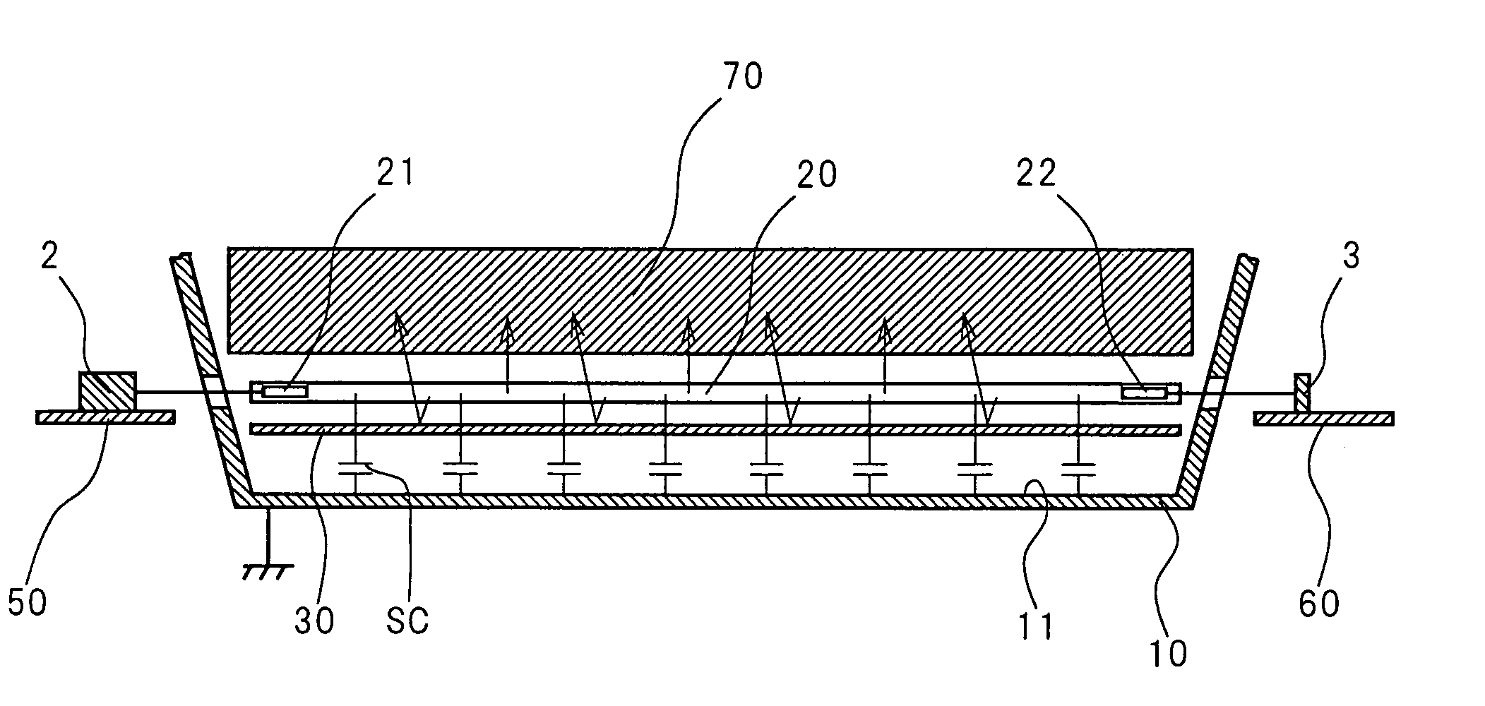
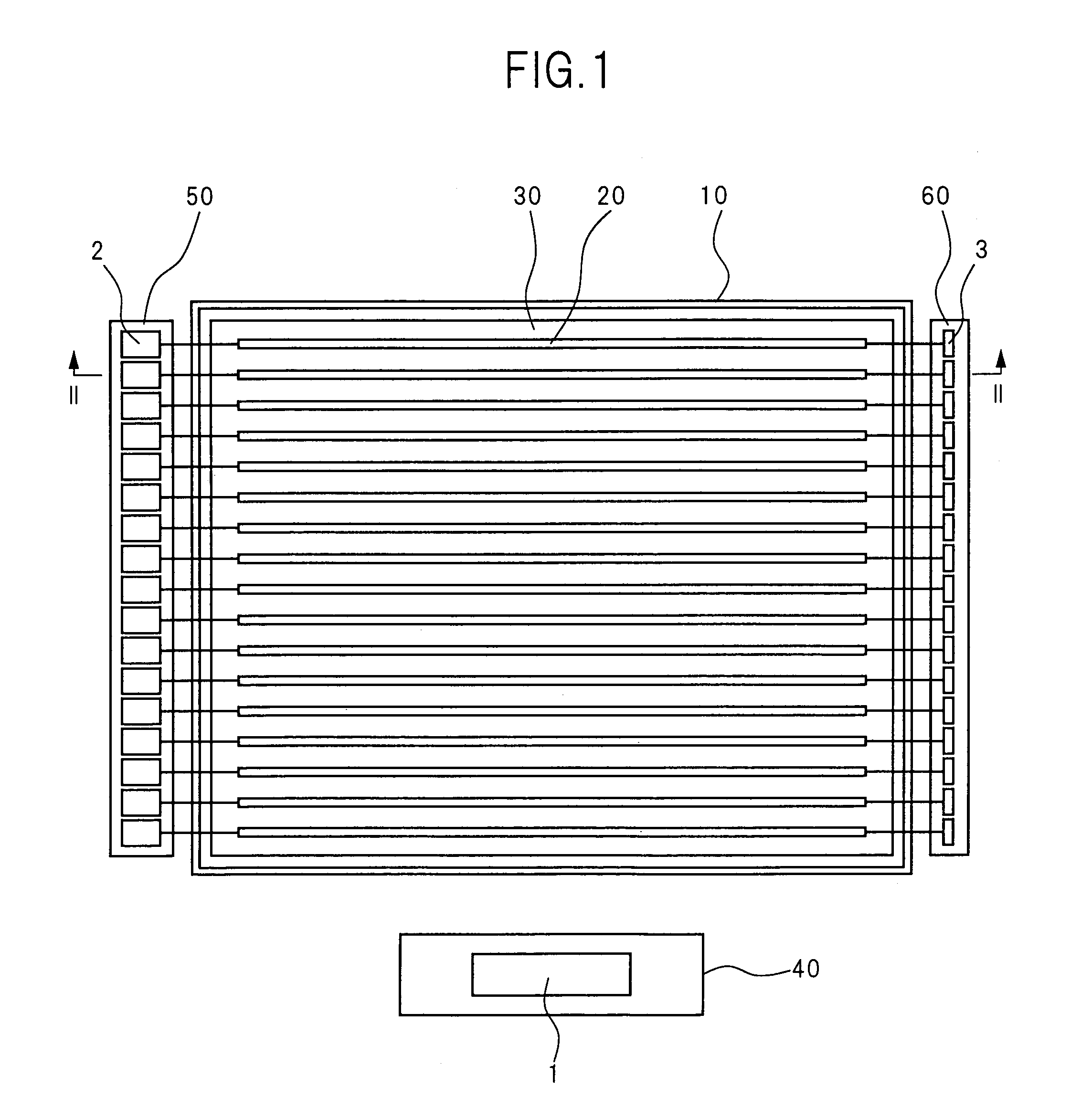
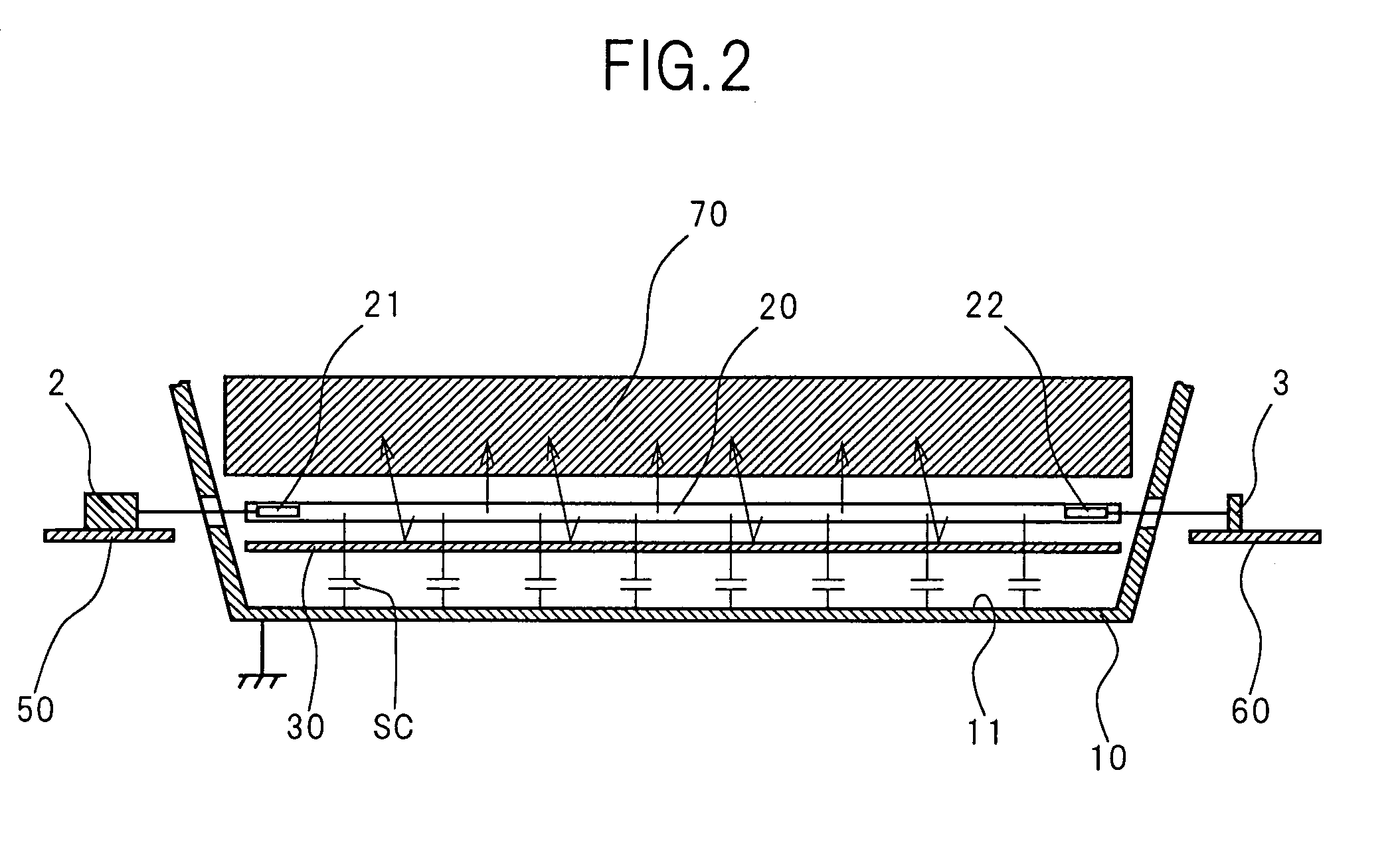
[0065]FIG. 1 is a front view showing the inside of a liquid crystal display equipped with a CCFL driver circuit according to Embodiment 1 of the present invention. FIG. 2 is a cross-sectional view of the liquid crystal display taken along the line II—II shown in FIG. 1. The arrows shown in FIG. 1 represent the eye direction. This liquid crystal display comprises a case 10, more than one CCFL 20, a reflector 30, a first circuit board 40, a second circuit board 50, a third circuit board 60, and a liquid crystal panel 70. The CCFL driver circuit according to Embodiment 1 of the present invention is mainly divided into three blocks 1, 2, and 3, which are mounted on the first circuit board 40, the second circuit board 50, and the third circuit board 60, respectively.

[0066]The case 10 is, for example, a metallic box that is grounded. The front side of the case 10 is open. The reflector 30, the CCFLs 20, and the liquid crystal panel 70 (not shown in FIG. 1) are placed in order from the bac...

embodiment 2

[0087]A CCFL driver circuit according to Embodiment 2 of the present invention is installed into a liquid crystal display in a manner similar to that of the circuit according to the above-described Embodiment 1. The structure of the liquid crystal display is similar to the structure according to the above-described Embodiment 1, and hence, the description of the structure cites FIGS. 1 and 2 and the description for the above-described Embodiment 1.

[0088]FIG. 7 is the circuit diagram showing the configuration of the CCFL driver circuit according to Embodiment 2 of the present invention. The CCFL driver circuit comprises components similar to the components of the circuit according to Embodiment 1 (cf. FIG. 3), except the configuration of the first block 1. Accordingly, those similar components are marked with the same reference symbols as the reference symbols shown in FIG. 3, and the description of them cites the descriptions for Embodiment 1.

[0089]A first block 1 includes a oscilla...

embodiment 3

[0093]A CCFL driver circuit according to Embodiment 3 of the present invention is installed into a liquid crystal display in a manner similar to that of the circuit according to the above-described Embodiment 1. The structure of the liquid crystal display is similar to the structure according to the above-described Embodiment 1, and hence, the description of the structure cites FIGS. 1 and 2 and the description for the above-described Embodiment 1.

[0094]FIG. 8 is the circuit diagram showing the configuration of the CCFL driver circuit according to Embodiment 3 of the present invention. The CCFL driver circuit comprises components similar to the components of the circuit according to Embodiment 1 (cf. FIG. 3), except the configuration of the second block 2 and the third block 3. Accordingly, those similar components are marked with the same reference symbols as the reference symbols shown in FIG. 3, and the description of them cites the descriptions for Embodiment 1.

[0095]In general,...


PUM

PropertyMeasurementUnit
constant frequencyaaaaaaaaaa
lamp voltageaaaaaaaaaa
frequencyaaaaaaaaaa

Abstract

A first block (1) converts a DC voltage (Vi) into an AC voltage (V) of a high frequency, using a high-frequency oscillator circuit (4) and a step-up transformer (5). The first block (1) acts as a low-impedance power supply owing to suppression of leakage flux in the step-up transformer (5). A second block (2) and a third block (3) are connected to each CCFL (20). A ballast inductor (LB) causes the CCFL (20) to shine through the resonance with a matching capacitor (CM), and then maintains the stable lamp current during shining of the CCFL (20). The capacitance of the matching capacitor (CM) is separately adjusted for each CCFL (20), and thereby, the total impedance of the matching capacitor (CM) and the surrounding stray capacitances is matched to the impedance of the series connection of the ballast inductor (LB) and an overcurrent protection capacitor (CP).

Description

BACKGROUND OF THE INVENTION[0001]The present invention relates to a circuit for driving a cold cathode fluorescent lamp (CCFL) and, in particular, the circuit for driving more than one CCFL.[0002]A fluorescent lamp is broadly divided into a hot-cathode type and a cold-cathode type by constituent of the electrodes. In the cold cathode fluorescent lamp (CCFL), the electrodes consist of materials that radiate many electrons due to high voltages applied. In other words, the electrodes include no filament for thermionic emission, in contrast to the hot cathode fluorescent lamp. Thereby, the CCFL has the advantages over the hot cathode fluorescent lamp especially in its much smaller diameter tube, its longer life, and its lower power consumption. Because of these advantages, the CCFLs are extensively used for, in particular, the products strongly required to reduce the thickness (or size) and lower the power consumption, such as the backlights of liquid crystal displays and the light sour...

Claims


Application Information

Patent Timeline
Patent Type & Authority Patents(United States)
IPC IPC(8): H05B37/00G02F1/13357F21S2/00F21Y103/00H01F38/08H05B41/02H05B41/232H05B41/24H05B41/282H05B41/295
CPCH05B41/2822G02F1/133604G02F2001/133612G02F1/133612H05B41/295
Inventor KOMATSU, AKEYUKIMIYAKE, EIJIKAWATAKA, KENJI
Owner PANASONIC CORP
Why Eureka
Try Eureka