Electropneumatic horn

a technology of electropneumatic horns and horns, applied in the direction of mechanical vibration separation, hydraulic/pneumatic audible signalling, sound producing devices, etc., can solve the problems of inability to carry out correct assembly, difficult connection between each acoustic unit and the compressor, time-consuming and labor-intensive, etc., to achieve less acoustic power, reduce the path of compressed air flow, and increase the sound instantaneous

Inactive Publication Date: 2006-05-02
STEBEL
View PDF12 Cites 12 Cited by
  • Summary
  • Abstract
  • Description
  • Claims
  • Application Information

AI Technical Summary

Benefits of technology

[0036]Still advantageously, the compact structure of the acoustic horn minimizes the paths of the compressed air flows from the compressor to the acoustic chambers thus increasing the performance as to sound instantaneousness and contemporaneousness when more acoustic ducts are provided.
[0037]Also advantageously the compact structure of the acoustic horn allows more favourable installations for sound propagation from the vehicles, still respecting the minimum values for the type approval, more particularly in comparison with the electromagnetic horn of substantially less acoustic power.

Problems solved by technology

A first drawback of such horns consists of the assembling complexity in the installation phase because bracketing of two or more components corresponding to the compressor and the acoustic units is required.
Another drawback consists in that the connection between each acoustic unit and the compressor is difficult and time consuming and does not warrant when improperly effected, instantaneousness and contemporaneousness of sound of the acoustic units.
As a matter of fact it is often impossible to carry out a correct assembly, more particularly with regard to the air connection between compressor and sound wave generator, thus making impossible to mount in limited space several components divided from each other but at the same time requiring to be installed close to each other to obtain sound instantaneousness and with the acoustic ducts being equidistant from the compressor to warrant contemporaneousness of sound.
However, the assembling phase of said electromagnetic horns requires the use of special brackets, which are essential for their operation and have the drawback of increasing the overall dimensions of the assembly.

Method used


Image

  • Electropneumatic horn
  • Electropneumatic horn
  • Electropneumatic horn

Examples


Embodiment Construction

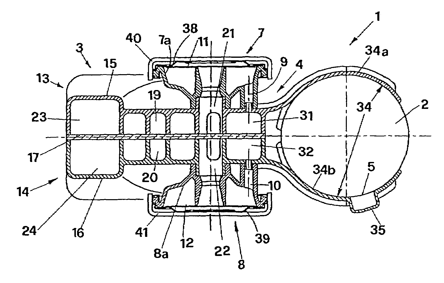
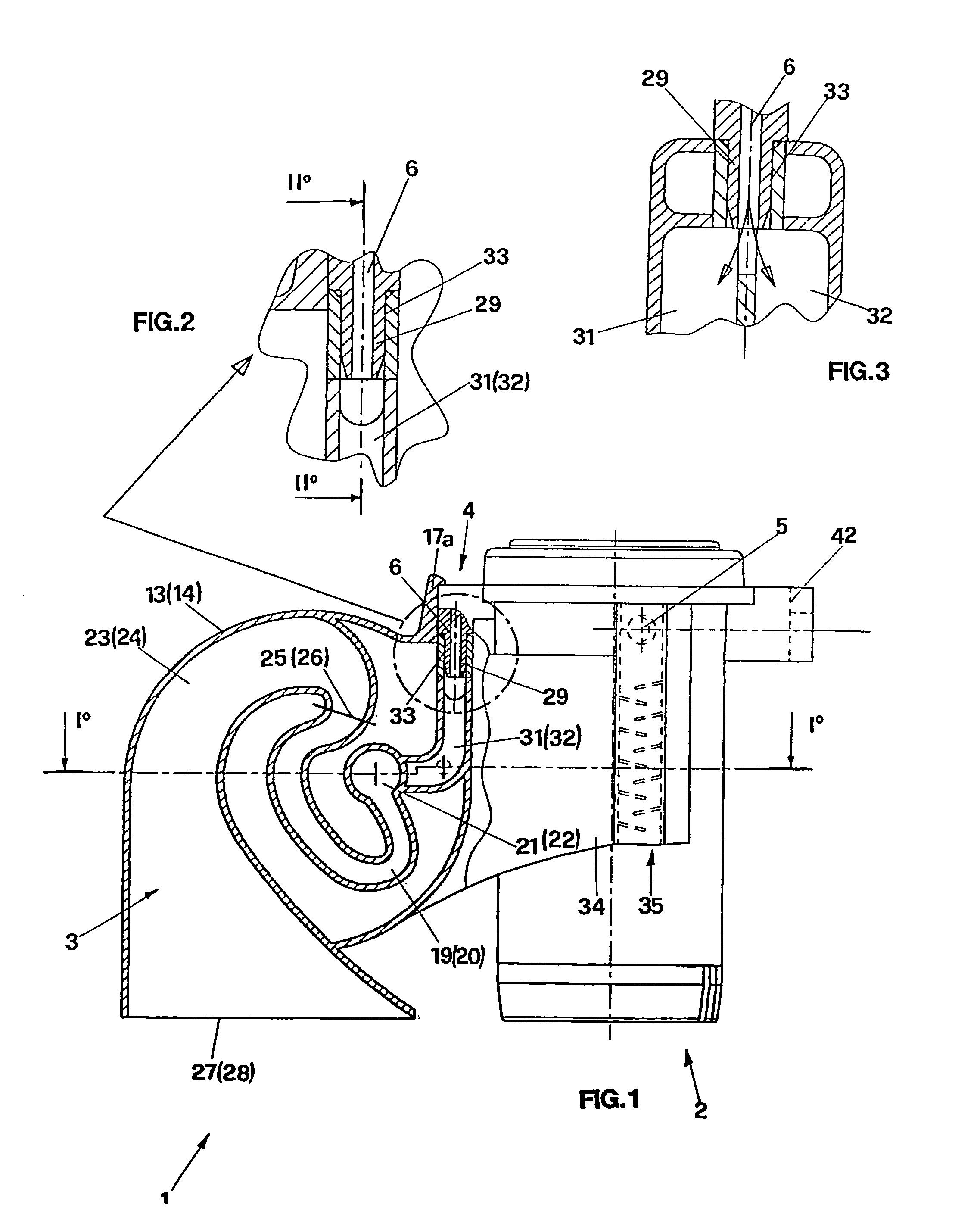
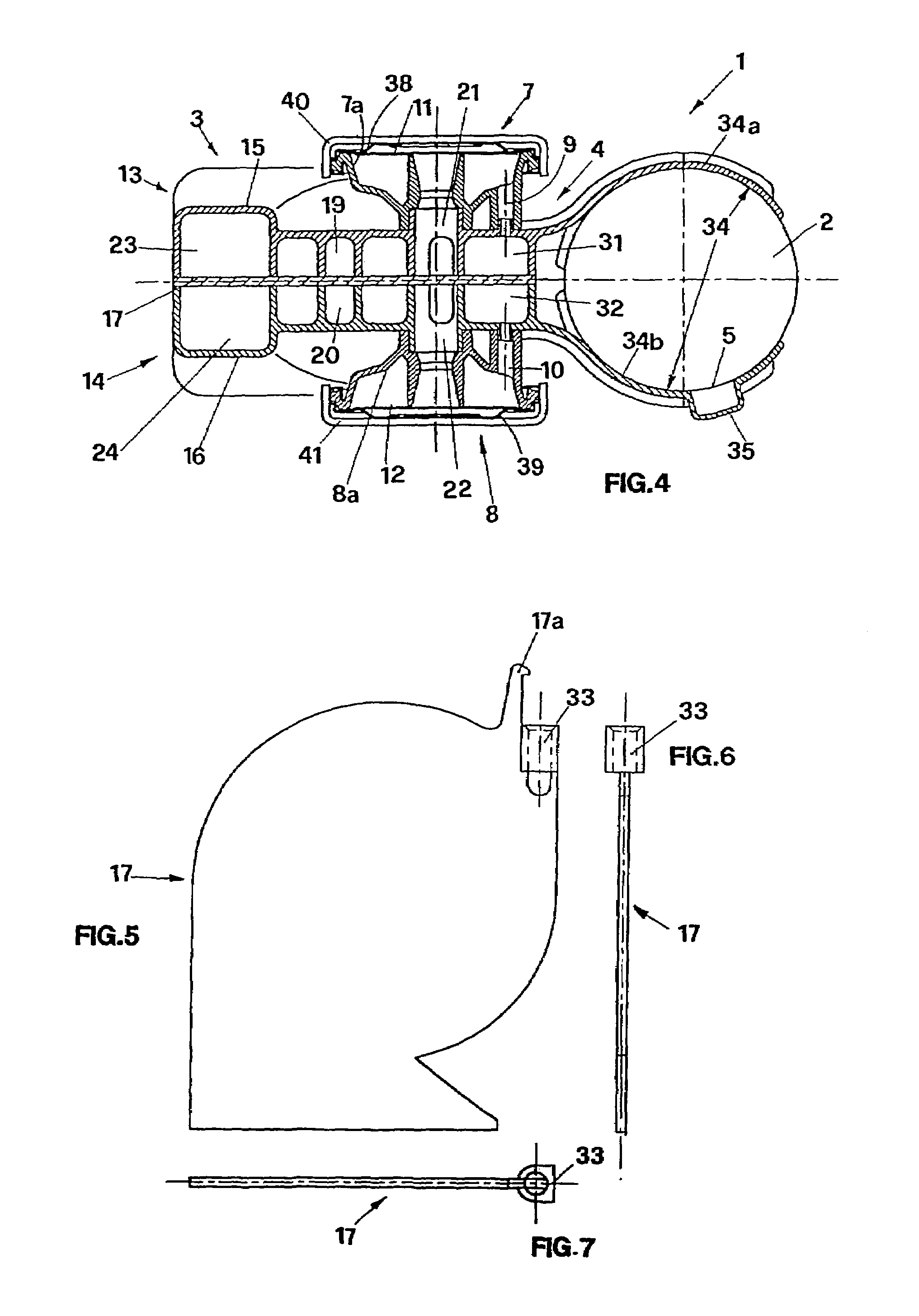
[0057]The acoustic horn of the invention is shown in FIG. 1 where it is generally indicated with numeral 1.

[0058]The horn comprises a compressor unit 2, a sound wave generator 3 and air channelling means 4 adapted to put the compressor 2 in communication with the sound wave generator 3.

[0059]More particularly the compressor unit 2 is provided with a suction inlet 5 from which air from outside is sucked, and an outlet 6 for the compressed air.

[0060]Proper elements of connection to the power supply, not shown in the drawings for sake of simplicity, are provided in the body of the compressor 2 and are generally arranged in its lower part.

[0061]With regard now to the sound wave generator 3, it comprises two acoustic chambers indicated with numerals 7 and 8 in FIG. 4 respectively, each chamber being provided with an opening 9, 10, for introduction of pressurised air.

[0062]In each acoustic chamber 7, 8, there is an elastic membrane 11, 12, for sound generation when the membrane is being v...


PUM


Abstract

An electropneumatic acoustic horn is disclosed, comprising an electric compressor unit for generating compressed air and a sound wave generator comprising at least an acoustic chamber associated to at least a volute wound acoustic duct adapted to propagate the produced sound to the outside. Air channelling means put the compressor unit in communication with each acoustic chamber. The compressor unit and the sound wave generator are mechanically connected in a removable way by fitting slidingly a collar.

Description

BACKGROUND OF THE INVENTION[0001]The present invention relates to an electropneumatic horn particularly adapted to equip two- and four-wheeled motor vehicles.[0002]The electropneumatic horns of the prior art comprise a generator of sound waves including one or more acoustic units, connected to an electric compressor by ducts for air passage to generate a mono, bi o tri tonal tuned sound according to the number of acoustic units.[0003]More particularly the acoustic units consist of a straight exponential duct of a length proportional to the frequency to be reproduced, inserted in an acoustic chamber in which a membrane free to move with a reciprocating motion is arranged.[0004]The straight duct comprises a first stretch with generally constant section, provided with an inlet mouth for the sound signal generated by the oscillating membrane and a second stretch having a section varying with a generally conic exponential law ending with an outlet mouth for the amplified sound signal.[00...

Claims


Application Information

Patent Timeline
Patent Type & Authority Patents(United States)
IPC IPC(8): G08B3/00H04R1/30G10K1/00G10K9/04H04R23/00
CPCG10K9/04
Inventor DI GIOVANNI, CORRADOBELTRAME, LUIGI FILIPPO
Owner STEBEL
Why Eureka
Try Eureka