Array antenna including a monolithic antenna feed assembly and related methods

a monolithic, array antenna technology, applied in the field of communication, can solve the problems of reducing losses to surrounding surfaces, difficult mounting of antennas, and time-consuming individual coupling of feed line organizer bodies to the ground plane, and achieve the effect of straightforward production

Active Publication Date: 2006-05-02
HARRIS CORP
View PDF6 Cites 33 Cited by
  • Summary
  • Abstract
  • Description
  • Claims
  • Application Information

AI Technical Summary

Benefits of technology

[0005]In view of the foregoing background, it is therefore an object of the present invention to provide an array antenna that is relatively straightforward to produce, particularly with respect to the antenna feed assembly.

Problems solved by technology

While a printed circuit antenna is advantageous in applications requiring a conformal configuration, e.g., in aerospace systems, mounting the antenna presents challenges.
One of these challenges is with respect to the manner in which it is fed such that conformality and satisfactory radiation coverage and directivity are maintained and losses to surrounding surfaces are reduced.
Although this patent discloses a significant advance in such antennas, individually coupling the feed line organizer bodies to the ground plane is a tedious and time consuming process, especially when the phased array antenna includes a large number of antenna elements.
In addition, manufacturing costs may be increased as a result of this process.

Method used


Image

  • Array antenna including a monolithic antenna feed assembly and related methods
  • Array antenna including a monolithic antenna feed assembly and related methods
  • Array antenna including a monolithic antenna feed assembly and related methods

Examples


Embodiment Construction

[0022]The present invention will now be described more fully hereinafter with reference to the accompanying drawings, in which preferred embodiments of the invention are shown. This invention may, however, be embodied in many different forms and should not be construed as limited to the embodiments set forth herein. Rather, these embodiments are provided so that this disclosure will be thorough and complete, and will fully convey the scope of the invention to those skilled in the art. Like numbers refer to like elements throughout.

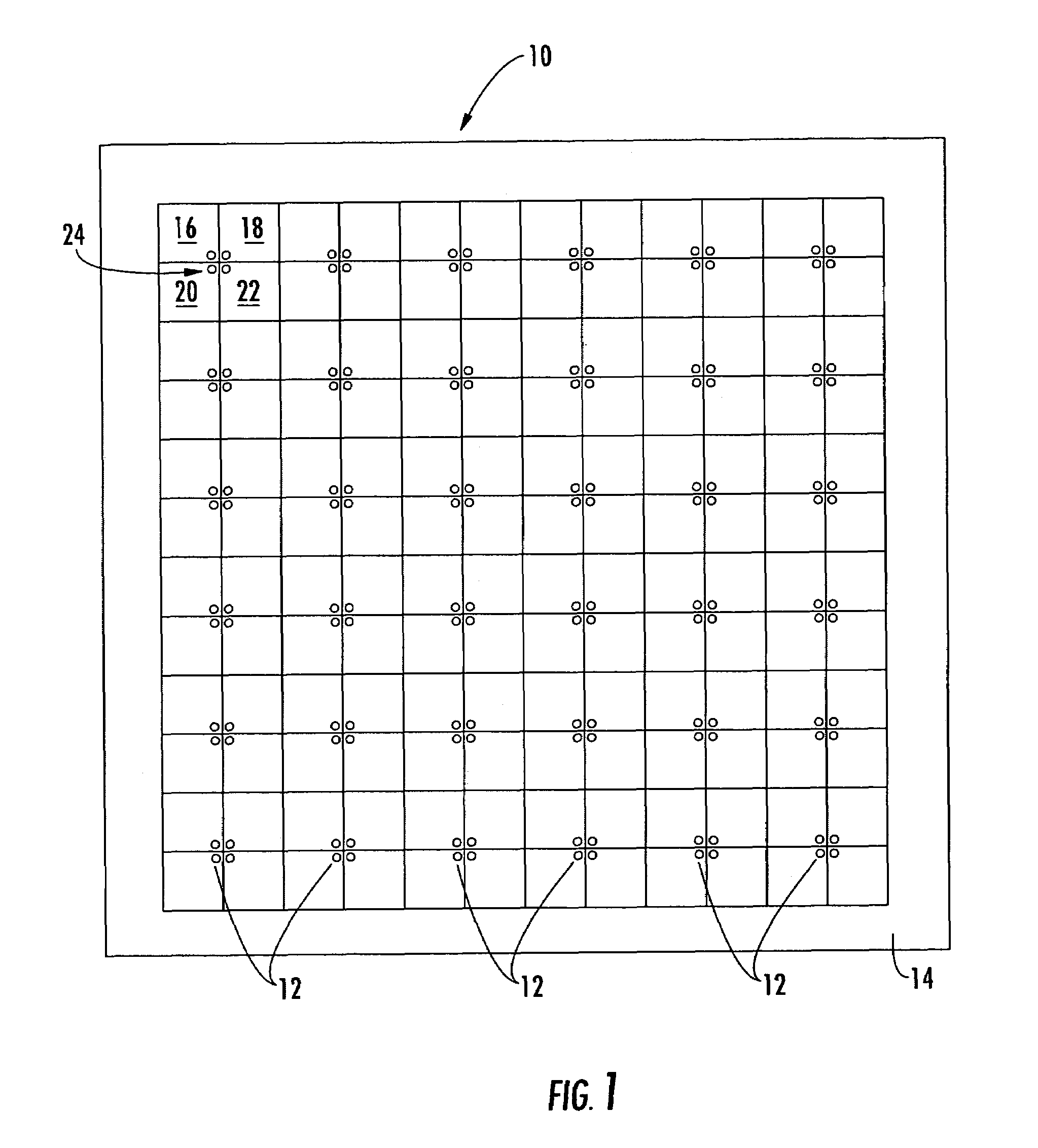
[0023]Referring initially to FIG. 1, an antenna 10 according to the invention includes a plurality of antenna units 12 arranged in an array. The illustrated antenna 10 includes 36 antenna units 12 formed on a printed conductive sheet 14, where each antenna unit includes four adjacent dipole antenna elements 16, 18, 20, 22 arranged in a spaced apart relation from one another about a central feed position 24. The 36 antenna units 12 are for illustrative purp...


PUM


Abstract

An antenna includes antenna elements, an antenna feed assembly and at least one integrated circuit adjacent the antenna feed assembly on a side thereof opposite the antenna elements. The at least one integrated circuit is connected to the antenna elements via the antenna feed assembly. The antenna feed assembly includes a conductive base plate spaced from the antenna elements, and has feed openings therein. Spaced apart conductive posts are integrally formed with the conductive base plate as a monolithic unit, and extend outwardly therefrom toward the antenna elements. Each conductive post has at least one passageway therethrough aligned with at least one respective feed opening to define at least one antenna feed passageway. A respective elongated feed conductor extends through each antenna feed passageway.

Description

FIELD OF THE INVENTION[0001]The present invention relates to the field of communications, and more particularly, to phased array antennas.BACKGROUND OF THE INVENTION[0002]Existing phased array antennas include a wide variety of configurations for various applications, such as satellite reception and remote broadcasting. The desirable characteristics of low cost, light-weight, low profile and mass producibility are provided in general by printed circuit antennas. Printed circuit antennas are defined by flat conductive elements spaced from a single, essentially continuous ground element by a dielectric sheet of uniform thickness.[0003]While a printed circuit antenna is advantageous in applications requiring a conformal configuration, e.g., in aerospace systems, mounting the antenna presents challenges. One of these challenges is with respect to the manner in which it is fed such that conformality and satisfactory radiation coverage and directivity are maintained and losses to surround...

Claims


Application Information

Patent Timeline
Patent Type & Authority Patents(United States)
IPC IPC(8): H01Q1/38
CPCH01Q21/062H01Q21/0093H01Q21/0006H01L2223/6677
Inventor TAYLOR, ROBERT C.CROSWELL, WILLIAM F.HASH, RONALD J.
Owner HARRIS CORP
Why Eureka
Try Eureka