Magnetic recording medium having a specific relation of coercive force HC and residual magnetization MR in perpendicular direction to substrate surface

a magnetic recording medium and specific relation technology, applied in special recording techniques, instruments, record information storage, etc., to achieve excellent thermal disturbance resistance, improve recording performance and information retention performance of magnetic recording medium, and record minute magnetic domains in recording layer with ease

Inactive Publication Date: 2006-05-02
HITACHT MAXELL LTD
View PDF5 Cites 37 Cited by
  • Summary
  • Abstract
  • Description
  • Claims
  • Application Information

AI Technical Summary

Benefits of technology

[0060]When (Ku—2πMs2) is negative, the magnetic functional layer is the in-plane magnetized layer. When (Ku—2πMs2) is positive, the magnetic functional layer is the perpendicular magnetized film. When (Ku—2πMs2) is negative, i.e., when the magnetic functional layer is the in-plane magnetized film, it is preferable that the axis of easy magnetization is in the in-plane direction and in the direction perpendicular to the recording track. That is, it is necessary to provide such a magnetic characteristic that the coercive force of the magnetic functional layer is in the in-plane direction and in the direction perpendicular to the recording track. On the other hand, when (Ku—2πMs2) is positive, i.e., when the magnetic functional layer is the perpendicular magnetized film, it is necessary to provide the coercive force when the measurement is performed in the in-plane direction. In order to realize the magnetic characteristic as described above, it is preferable that the magnetic functional layer has a dispersion or variance of perpendicular magnetic anisotropy. The method for applying th...

Problems solved by technology

As the information network is developed and the multimedia comes into the widespread use, the magnetic disk apparatus, which is the major information-recording appa...

Method used


Image

  • Magnetic recording medium having a specific relation of coercive force HC and residual magnetization MR in perpendicular direction to substrate surface
  • Magnetic recording medium having a specific relation of coercive force HC and residual magnetization MR in perpendicular direction to substrate surface
  • Magnetic recording medium having a specific relation of coercive force HC and residual magnetization MR in perpendicular direction to substrate surface

Examples


example 1

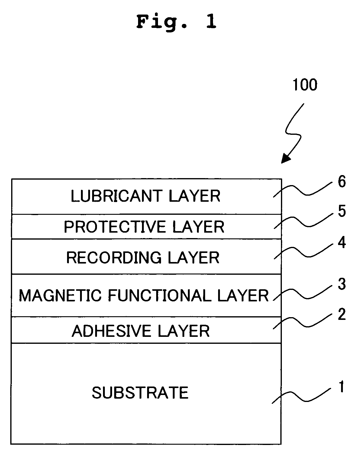
[0115]FIG. 1 shows a schematic cross section of a magnetic recording medium 100. The magnetic recording medium 100 has an adhesive layer 2, a magnetic functional layer 3, a recording layer 4, a protective layer 5, and a lubricant layer 6 which are provided in this order on a substrate 1. An oxygen-added PtCo alloy was used for the magnetic functional layer 3, and a Co / Pd multi layer thin film was used for the recording layer 4. The perpendicular magnetic recording medium 100 having the stacked structure as described above was principally formed by means of the magnetron sputtering method. The arrival vacuum degree during the sputtering was set to high vacuum as compared with 5×10⁻⁶ Pa for each of the layers. Ar gas, Kr gas, or mixed gas based on these gases, which had a purity of not less than 6 N, was principally used for the sputtering gas. The substrate temperature during the film formation or deposition was room temperature. An explanation will be made below about the method for...

example 2

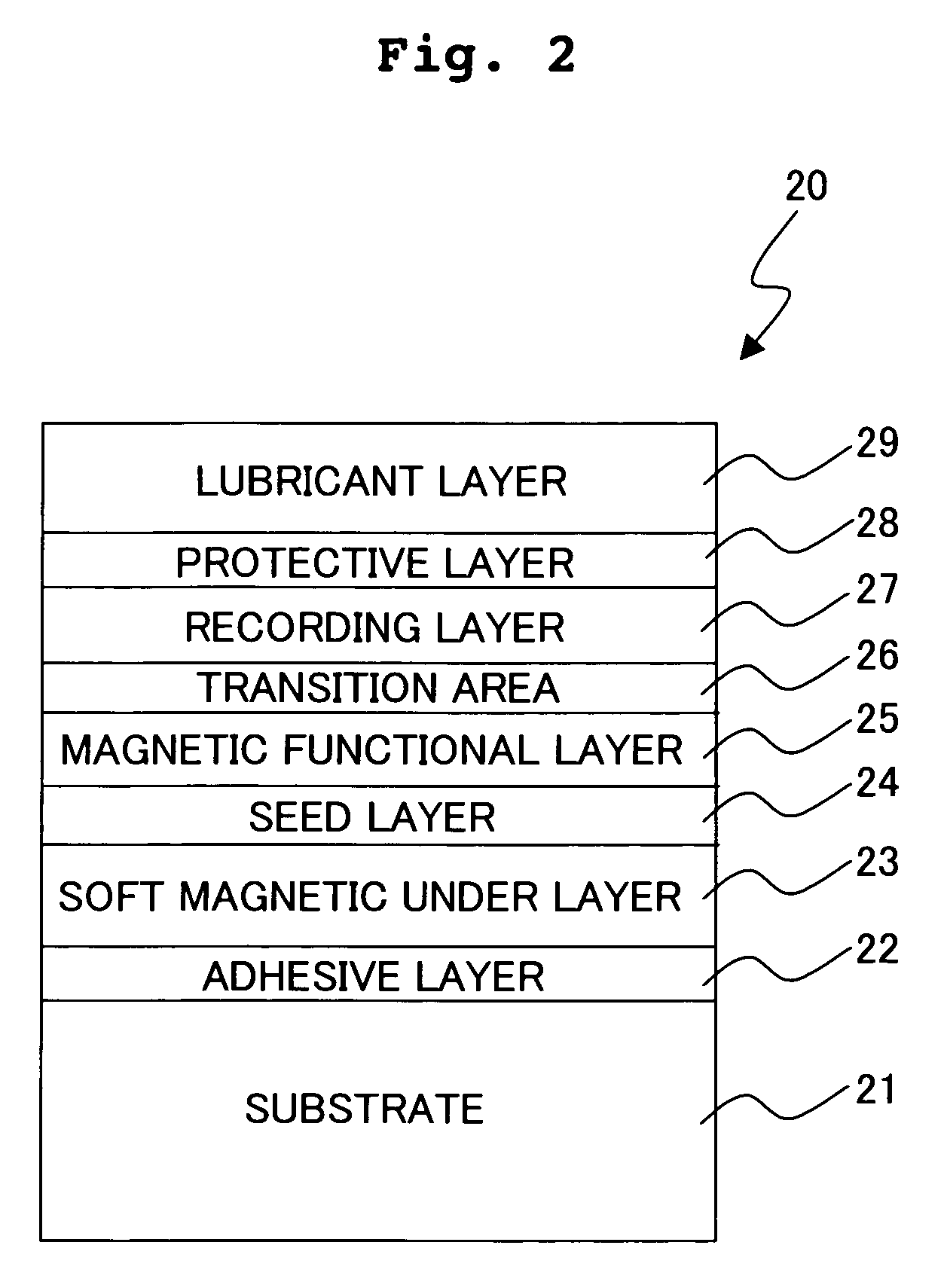
[0126]Next, an embodiment of the magnetic recording medium is shown, in which multi layer thin films of Co and Pd were used for both of a recording layer and a magnetic functional layer. FIG. 2 shows a schematic sectional view illustrating the magnetic recording medium 20.

Adhesive Layer

[0127]An adhesive layer 22 was formed on a glass substrate 21 in the same manner as in Example 1.

Soft Magnetic Under Layer

[0128]Subsequently, a soft magnetic under layer 23 was stacked on the adhesive layer 22. Fe79Ta9C12 was used as a material, and the film was formed to have a thickness of 200 nm. Further, Fe79Ta9C12, which was formed as the film, was heated for 30 seconds at a temperature of 450° C. by using a carbon heater in vacuum, followed by being gradually cooled.

Seed Layer

[0129]Subsequently, a seed layer 24 was formed as a layer to optimally control the crystalline orientation of the recording layer 27. In this example, Pd60B40 was formed to have a thickness of 5 nm as the seed layer 24 on t...

example 3

[0135]Still another different embodiment of the present invention will be explained with reference to FIG. 4. FIG. 4 shows a schematic sectional view of a magnetic recording medium manufactured in Example 3. As shown in FIG. 4, the magnetic recording medium 40 has a structure comprising a first under layer 42, a magnetic functional layer 43, a second under layer 44, a recording layer 45, a protective layer 46, and a lubricant layer 47 which are successively stacked on a substrate 41. CoCr-based polycrystalline films, specifically CoCrPt films added with oxygen were used for both of the magnetic functional layer 43 and the recording layer 45. The magnetic functional layer 43 has the axis of easy magnetization in the in-plane direction, and the recording layer 45 has the axis of easy magnetization in the direction perpendicular to the film surface. The directions of the axes of easy magnetization of the magnetic functional layer 43 and the recording layer 45 were controlled by control...


PUM


Abstract

A perpendicular magnetic recording medium has a substrate, a magnetic functional layer provided on the substrate, and a magnetic recording layer stacked in contact with the magnetic functional layer and having perpendicular magnetic anisotropy. −4×2πMs2≦Ku≦6×2πMs2 is satisfied, wherein Ku represents a perpendicular magnetic anisotropy constant of the magnetic functional layer and Ms represents a saturation magnetization. The magnetic moment of the magnetic functional layer is rotated in a direction of an applied magnetic field during the recording, and the magnetic moment acts on the magnetization of the recording layer in such a manner that the applied magnetic field is assisted thereby. Minute magnetic domains can be stably retained and excellent thermal disturbance resistance can be obtained.

Description

BACKGROUND OF THE INVENTION[0001]1. Field of the Invention[0002]The present invention relates to a perpendicular magnetic recording medium capable of recording information at a high density, a recording method therefor, and a magnetic recording apparatus provided with the magnetic recording medium.[0003]2. Description of the Related Art[0004]As the information network is developed and the multimedia comes into the widespread use, the magnetic disk apparatus, which is the major information-recording apparatus for supporting such circumstances, encounters important problems of the realization of small size, low price, and large capacity and the improvement in reliability. In such a situation, the perpendicular magnetic recording medium is noticed, which is strongly resistant to the thermal fluctuation as compared with the in-plane or longitudinal magnetic recording medium and on which the recording can be performed at a high density. As for the perpendicular magnetic recording medium,...

Claims


Application Information

Patent Timeline
IPC IPC(8): G11B5/02G11B5/127G11B5/64G11B5/66
CPCG11B5/02G11B5/1278G11B5/66G11B2005/0021G11B2005/0002G11B5/656G11B5/672
Inventor SHIMAZAKI, KATSUSUKEMATSUNUMA, SATOSHITAKEUCHI, TERUAKIOTA, NORIO
Owner HITACHT MAXELL LTD
Why Eureka
Try Eureka