Delay locked loop circuitry for clock delay adjustment

Inactive Publication Date: 2006-05-02
RAMBUS INC
View PDF39 Cites 33 Cited by
  • Summary
  • Abstract
  • Description
  • Claims
  • Application Information

AI Technical Summary

Benefits of technology

[0009]Preferably, the first DLL includes a control circuit with a digital memory for providing the desired delay adjustment

Problems solved by technology

This second order system has stability problems associated with its operation.
Furthermore, the VCO phase lock loop accumulates phase error in response to sudden change in phase on inputs to the loop, where the input includes not only the input clock but also the power supplies to the loop.
This causes the loop to be noise sensitive when the noise is in the form of sudden phase shifts.
Another drawback regarding the prior art patent is that the subloop used for generating the in-phase clock relies on the

Method used


Image

  • Delay locked loop circuitry for clock delay adjustment
  • Delay locked loop circuitry for clock delay adjustment
  • Delay locked loop circuitry for clock delay adjustment

Examples


Embodiment Construction

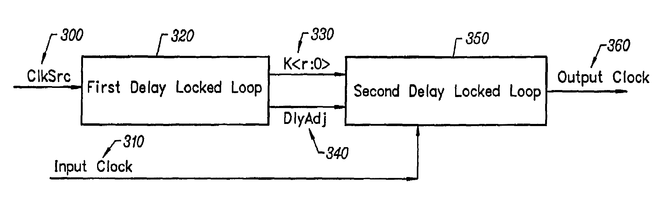
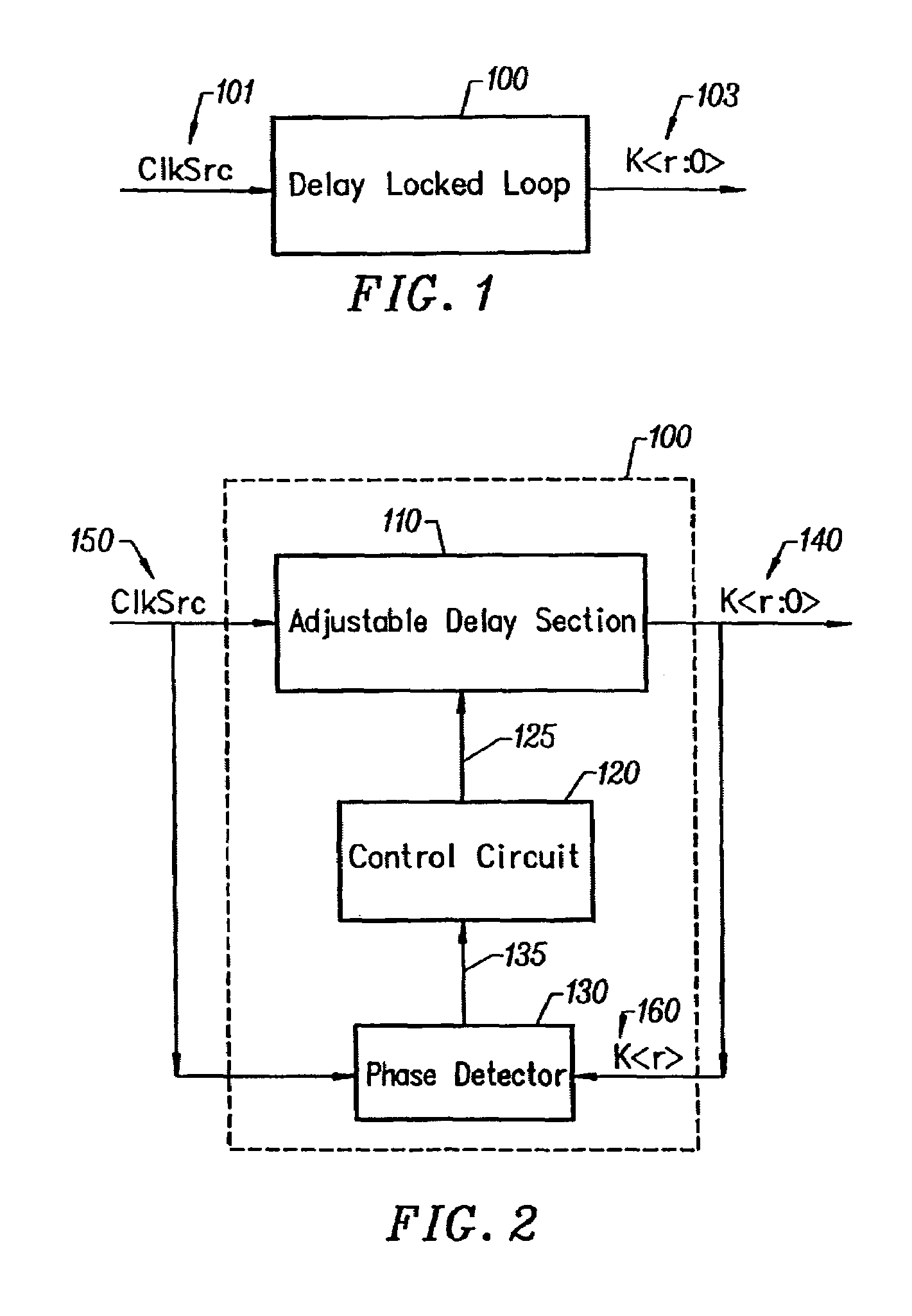
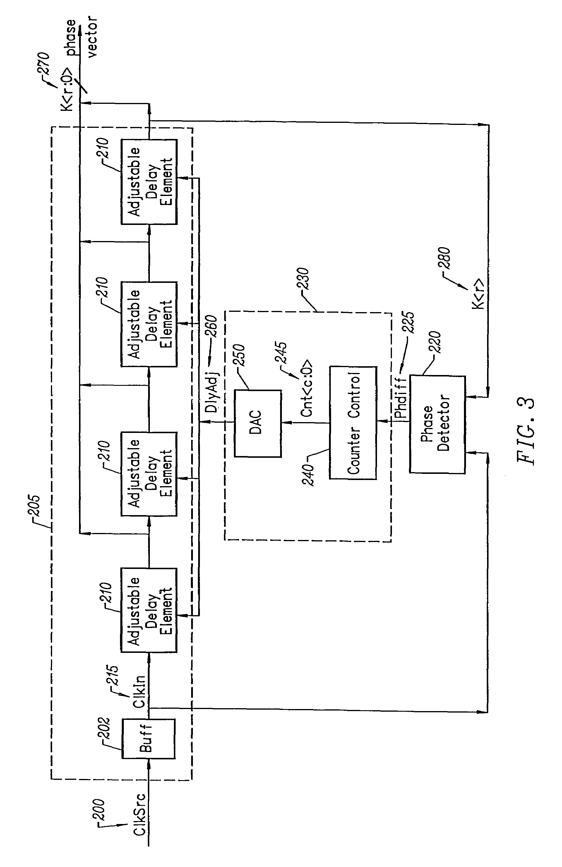
[0035]Embodiments of the present invention provide a method and circuitry to generate a set of phase vectors in a way that is more immune to noise on loop inputs including the power supplies, leading to a more stable set of phase vectors. Also, an output clock that has a predetermined phase relationship with an input clock is provided. The effect of clock buffer delays between the input clock and output clock is minimized. The delay of an adjustable delay element is adjusted with a counter and a digital to analog converter, the count in the counter digitally representing the current delay adjustment of the delay locked loop. The digital count is converted to a signal suitable for adjusting an adjustable delay element used in a delay locked loop.

[0036]The setting of current delay adjustment of the loop is digitally represented so that the setting may be stored while the loop is in a powered-down or low power state. There is quick re-acquisition of the locked state of a delay locked l...


PUM


Abstract

Delay locked loop circuitry for generating a predetermined phase relationship between a pair of clocks. A first delay-locked loop includes a delay elements arranged in a chain, the chain receiving an input clock and generating, from each delay element, a set of phase vectors, each shifted a unit delay from the adjacent vector. The first delay-locked loop adjusts the unit delays in the delay chain using a delay adjustment signal so that the phase vectors span a predetermined phase shift of the input clock. A second delay-locked loop selects, from the first delay-locked loop, a pair of phase vectors which brackets the phase of an input clock. A phase interpolator receives the selected pair of vectors and generates an output clock and a delayed output clock, the amount of the delay being controlled by the delay adjustment signal of the first delay-locked loop circuitry. A phase detector compares the delayed output clock with the input clock and adjusts the phase interpolator, based on the phase comparison, so that the phase of the delayed output clock is in phase with the input clock. As a result, there is a predetermined phase relationship between the output clock and the input clock, the phase relationship being the amount of delay between the output clock and the delayed output clock. Different phase relationships between the input and output clock are possible depending on the number of unit delays used in the path of the, delayed output clock or the output clock.

Description

[0001]This application is a continuation of patent application Ser. No. 09 / 524,402, filed Mar. 13, 2000, now U.S. Pat. No. 6,539,072 which was a continuation of patent application Ser. No. 08 / 795,657, filed Feb. 6, 1997, which issued as U.S. Pat. No. 6,125,157 on Sep. 26, 2000.BACKGROUND OF THE INVENTION[0002]The present invention relates to clock delay adjustment circuitry. In particular, the present invention relates to the generation of a set of phase vectors and the generation of output clocks that have precise phase relationships to an input clock.[0003]Previous art includes Rambus patent, U.S. Pat. No. 5,485,490, Leung and Horowitz, which discloses two independent loops, the first of which creates a fixed number of phase vectors, the second of which creates an output clock that is in phase with the input clock. Also disclosed in this patent is the use of separate circuitry to create a leading phase clock to the output clock by selecting a pair of phase vectors and interpolatin...

Claims


Application Information

Patent Timeline
IPC IPC(8): H03D3/24G06F1/10G11C7/22H03K5/00H03K5/13H03K5/24H03L7/07H03L7/081H04L7/00
CPCG06F1/10H04L7/0037G11C7/222H03K5/133H03K5/2481H03L7/07H03L7/0805H03L7/0812H03L7/0814G11C7/22H03K2005/00026H03K2005/00032H03K2005/00052H03K2005/00208H04L7/0008H04L7/0025H03L7/0816
Inventor DONNELLY, KEVIN S.CHAU, PAK SHINGHOROWITZ, MARK A.LEE, THOMAS H.JOHNSON, MARK G.LAU, BENEDICT C.YU, LEUNGGARLEPP, BRUNO W.CHAN, YIU-FAIKIM, JUNTRAN, CHANH VISTARK, DONALD C.NGUYEN, NHAT M.
Owner RAMBUS INC
Why Eureka
Try Eureka