
Method for production of tomographic section images of a periodically moving object with a number of focus detector combinations

a technology of focus detector and tomography, which is applied in the field of tomography section images, can solve the problems of large amount of measurement information that cannot be used, and the time resolution achieved when scanning a periodically moving heart is not sufficient to achieve sufficiently sharp image representations, so as to reduce the dose load of examination

Inactive Publication Date: 2006-05-02
SIEMENS HEALTHCARE GMBH
View PDF19 Cites 17 Cited by
  • Summary
  • Abstract
  • Description
  • Claims
  • Application Information

AI Technical Summary

Benefits of technology

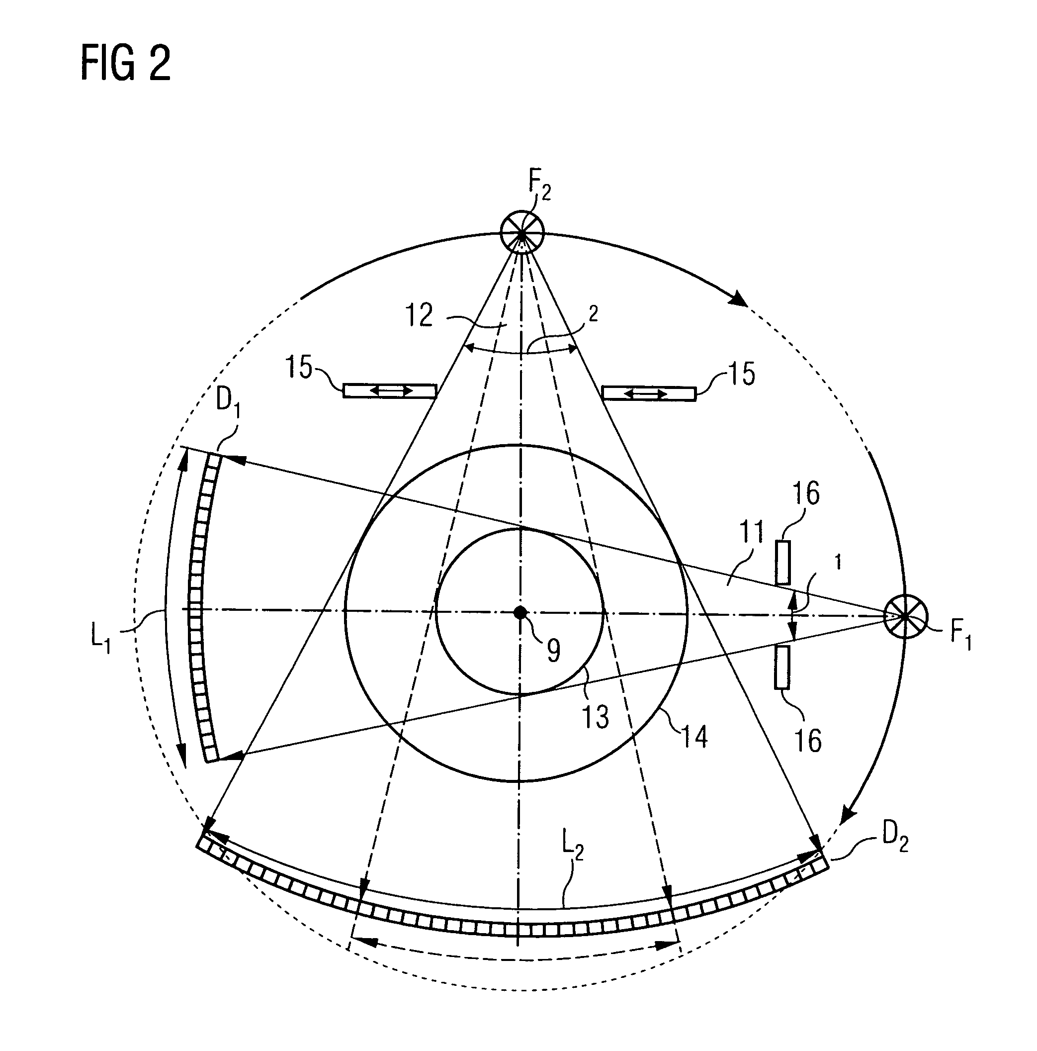
The invention provides a method for producing tomographic section images of a periodically moving examination object, such as a heart, with better time resolution. The method involves using a cardio-SMPR method, which involves a large number of incomplete segment images and simultaneously measuring the movement of the object using focus detector combinations. The movement signals are measured and recorded, and the detector output data is used to reconstruct the tomographic section images. The method can be carried out using two or three focus detector combinations, and the aperture angle of the larger detector combination can be restricted to match the other detector combination. The method also allows for the control of the radiation dose and the reduction of the dose load on the examination object.

Problems solved by technology

This means that a large amount of measurement information cannot be used since only measurement data at the correct time.
The problem of these known and so-called SMPR—or ACMPR—methods is that the time resolution that is achieved when scanning a periodically moving heart is not sufficient to achieve sufficiently sharp image representations.

Method used


Image

  • Method for production of tomographic section images of a periodically moving object with a number of focus detector combinations
  • Method for production of tomographic section images of a periodically moving object with a number of focus detector combinations
  • Method for production of tomographic section images of a periodically moving object with a number of focus detector combinations

Examples


Embodiment Construction

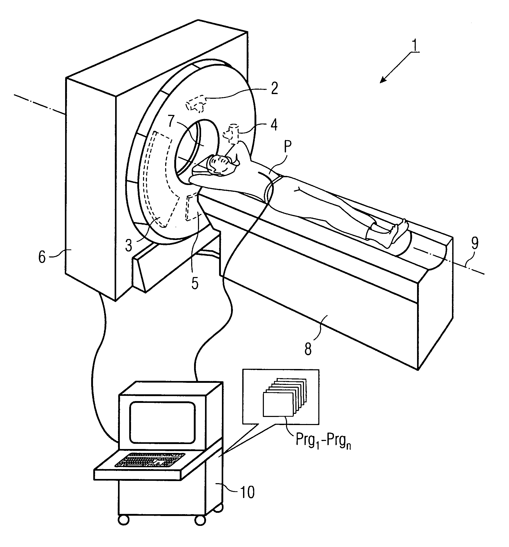
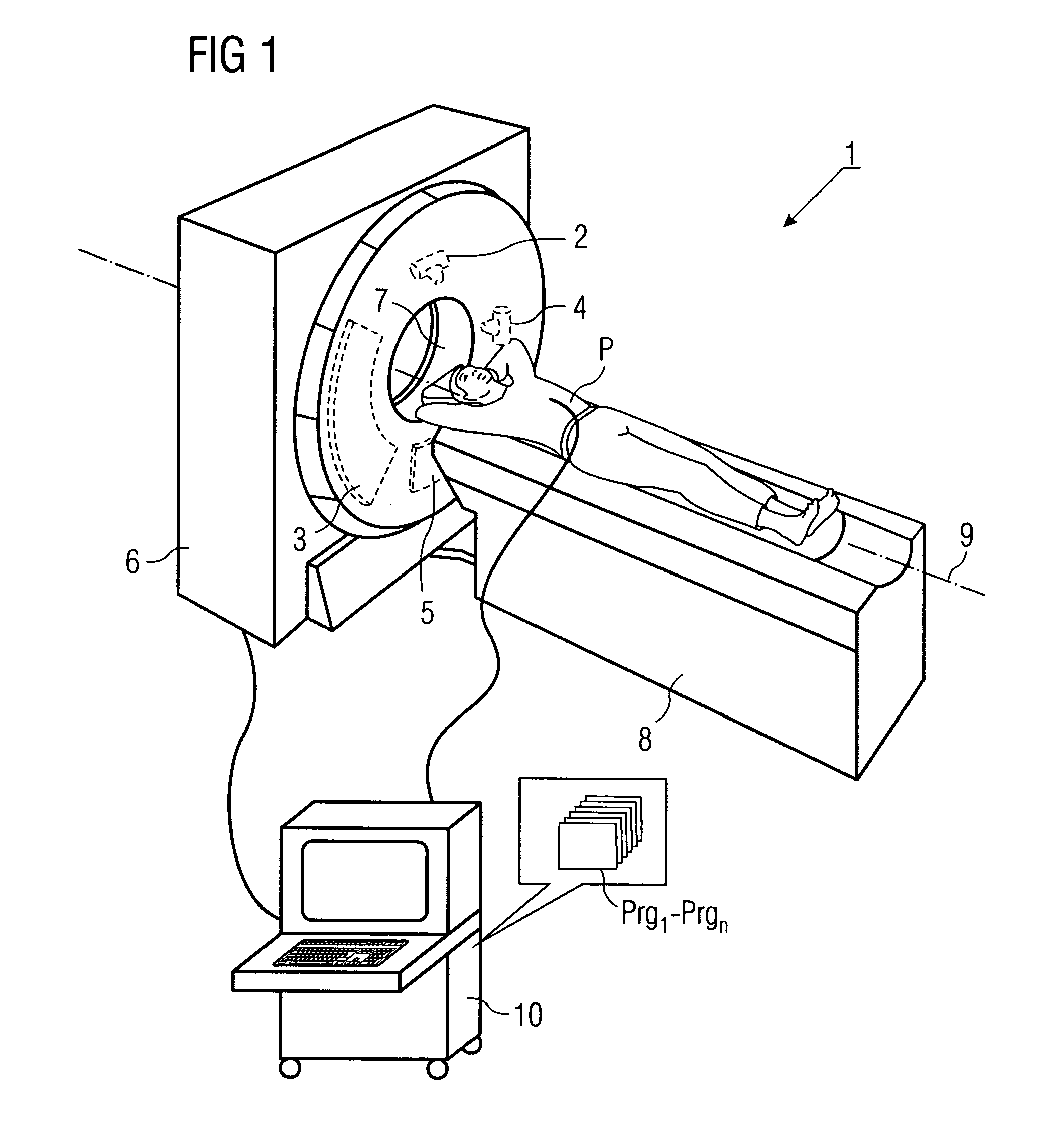
[0041]FIG. 1 shows a 3D illustration of one preferred exemplary embodiment of a CT scanner 1 with two focus detector combinations 2, 3, and 4, 5, which are mounted on a gantry (which is not illustrated) within the housing 6 such that they can rotate. The illustration shows only X-ray tubes 2 and 4, however, since the actual focus is located within the tube. Controlled by the control and evaluation unit 10 and by the control and evaluation programs Prgn integrated in it, the patient P is moved along the z axis 9 with the aid of the movable patient couch 8 through the opening 7 in the CT scanner 1, while the gantry is at the same time rotated, with the two focus detector combinations 2, 3 and 4, 5, about the z axis 9. With respect to the patient as the reference system, this results in spiral movement paths of the foci. If the foci are arranged on one plane, then each focus runs on its own spiral path SBn (see FIG. 4), which is shifted with respect to the other spiral path correspondi...


PUM


Abstract

A method and CT scanner are proposed for the production of tomographic section images, in particular X-ray CT images, of a periodically moving object with periodically changing movement and rest phases. For scanning, a number of focus detector combinations with flat detectors are moved on coaxial spiral paths and movement signals from the moving object are measured at the same time in order to detect movement and rest phases. Further, the time correlation between the movement data and the detector output data stored and axial segment image stacks are then reconstructed independently of one another from sub-segments of the spiral paths using the detector output data from each detector which represent a rest phase of the moving object. Additionally, segment image stacks from the n spiral paths of the n focus detector combinations at the correct time are added up in a complementary angle form and in layers to form 180° tomography section images. The axial segment image stacks are reconstructed in a first step from double-inclined reconstruction planes. Further, in a second step, they are reformatted to produce axial segment image stacks, and detector data from a number of successive movement periods are used for this purpose.

Description

[0001]This application claims priority on German application No. DE 10354214.0 filed on Nov. 20, 2003, the entire contents of which are hereby incorporated herein by reference.FIELD OF THE INVENTION[0002]The invention generally relates to a method for production of tomographic section images, in particular X-ray CT images, of a periodically moving object with periodically changing movement and rest phases. A number of focus detector combinations are moved around the examination object on coaxially running paths with the same pitch in order to scan the periodically moving examination object. Further, movement signals from the examination object at the same time are measured in order to determine movement and rest phases, and are stored correlated with the detector output signals.BACKGROUND OF THE INVENTION[0003]Computer tomography methods for creation of section images with the aid of multiple focus detector combinations are known, for example, from the patent specifications U.S. Pat...

Claims


Application Information

Patent Timeline
Patent Type & Authority Patents(United States)
IPC IPC(8): A61B6/00A61B6/03
CPCA61B6/032A61B6/4014A61B6/541A61B6/027A61B6/4085Y10S378/901A61B6/503
Inventor BRUDER, HERBERTFLOHR, THOMAS
Owner SIEMENS HEALTHCARE GMBH
Learn More