
Spatial decimation stimulation in an implantable neural stimulator, such as a cochlear implant

a cochlear implant and neural stimulation technology, applied in the field of implantable neural stimulation, can solve the problems of consuming excess power, consuming too much power, and implementing high-rate pulses in this region, and achieve the effect of high-rate stimulation and lower power level

Active Publication Date: 2006-05-02
ADVANCED BIONICS AG
View PDF20 Cites 84 Cited by
  • Summary
  • Abstract
  • Description
  • Claims
  • Application Information

AI Technical Summary

Benefits of technology

[0011]The present invention addresses the above and other needs by providing a cochlear (or other neural) implant that provides the benefits of high rate stimulation at a lower power level through the use of spatial decimation.
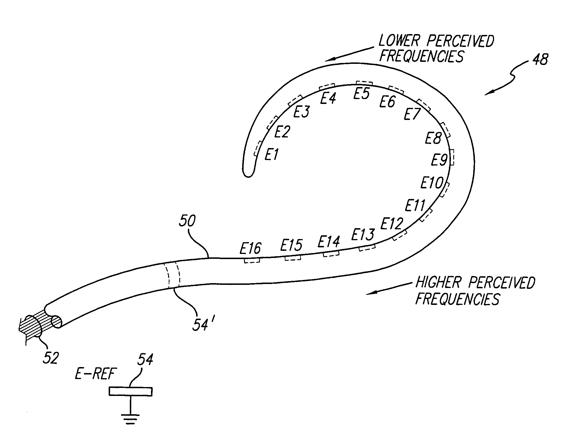
[0012]One object of the high-speed stimulation mode, available in a bionic ear implant system, is to desynchronize the auditory nerve. See, e.g, U.S. patent application Ser. No. 10 / 218,645, filed Aug. 13, 2002, assigned to the same assignee as is the present application, and incorporated herein by reference, as well as PCT Publication No. WO 03 / 015863 A2, previously referenced. Such desynchronization produces random states of neural polarization and depolarization, thereby providing a reduction in thresholds and an increase in electrical dynamic range. In the presence of low frequency stimulation, below the refraction crossover stimulation rate of the neurons, most people with normal hearing achieve a synchronized neural response even though, in the absence of this stimulation, random fluctuations in neural firing might occur. Thus, if synchronous neural firings occur in the low frequency range in the presence of stimulation, then the application of high-rate pulses in this region produces little benefit and consumes excess power. Hence, in accordance with the teachings of the present invention, spatial decimation is used to reduce the frequency at which narrow-width, high-amplitude, fast-rate pulses are provided to the apical regions of the cochlea, thereby saving power. Because the cochlea is tonotopoically arranged, low frequencies are represented or sensed by providing stimuli in the apical region of the cochlea, and high frequencies are represented or sensed by providing stimuli in the basal region of the cochlea. Thus, the present invention saves power by using spatial decimation to reduce the stimulation rate tonotopically as the applied stimuli approach the apex of the cochlea.
[0013]In accordance with one aspect of the invention, power is reduced in a cochlear implant system by reducing the stimulation rate tonotopically.
[0014]It accordance with another aspect of the invention, power is reduced in a cochlea implant system without noticeably degrading the important part of the stochastic resonance effect or the presentation of relevant temporal fine structure, which are important features offered by the fast-rate, narrow-width, high-amplitude pulses generated by a bionic-ear type of implant system.
[0016]Advantages offered by the present invention include, but are not necessarily limited to, the following: (1) the rate of stimulation to be applied to low-frequency regions of the cochlea may be significantly reduced at low frequencies below the refraction crossover rate and potentially into the crossover region based on patient performance; (2) the pulse width of pulses to be applied to low-frequency regions of the cochlea may be increased, thereby further reducing the power needed to generate adequate loudness growth; and (3) the forward telemetry data used by the implant system may be reduced, thereby providing a reduction in the forward telemetry bandwidth.

Problems solved by technology

Thus, if synchronous neural firings occur in the low frequency range in the presence of stimulation, then the application of high-rate pulses in this region produces little benefit and consumes excess power.

Method used


Image

  • Spatial decimation stimulation in an implantable neural stimulator, such as a cochlear implant
  • Spatial decimation stimulation in an implantable neural stimulator, such as a cochlear implant
  • Spatial decimation stimulation in an implantable neural stimulator, such as a cochlear implant

Examples


Embodiment Construction

[0024]The following description is of the best mode presently contemplated for carrying out the invention. This description is not to be taken in a limiting sense, but is made merely for the purpose of describing the general principles of the invention. The scope of the invention should be determined with reference to the claims.

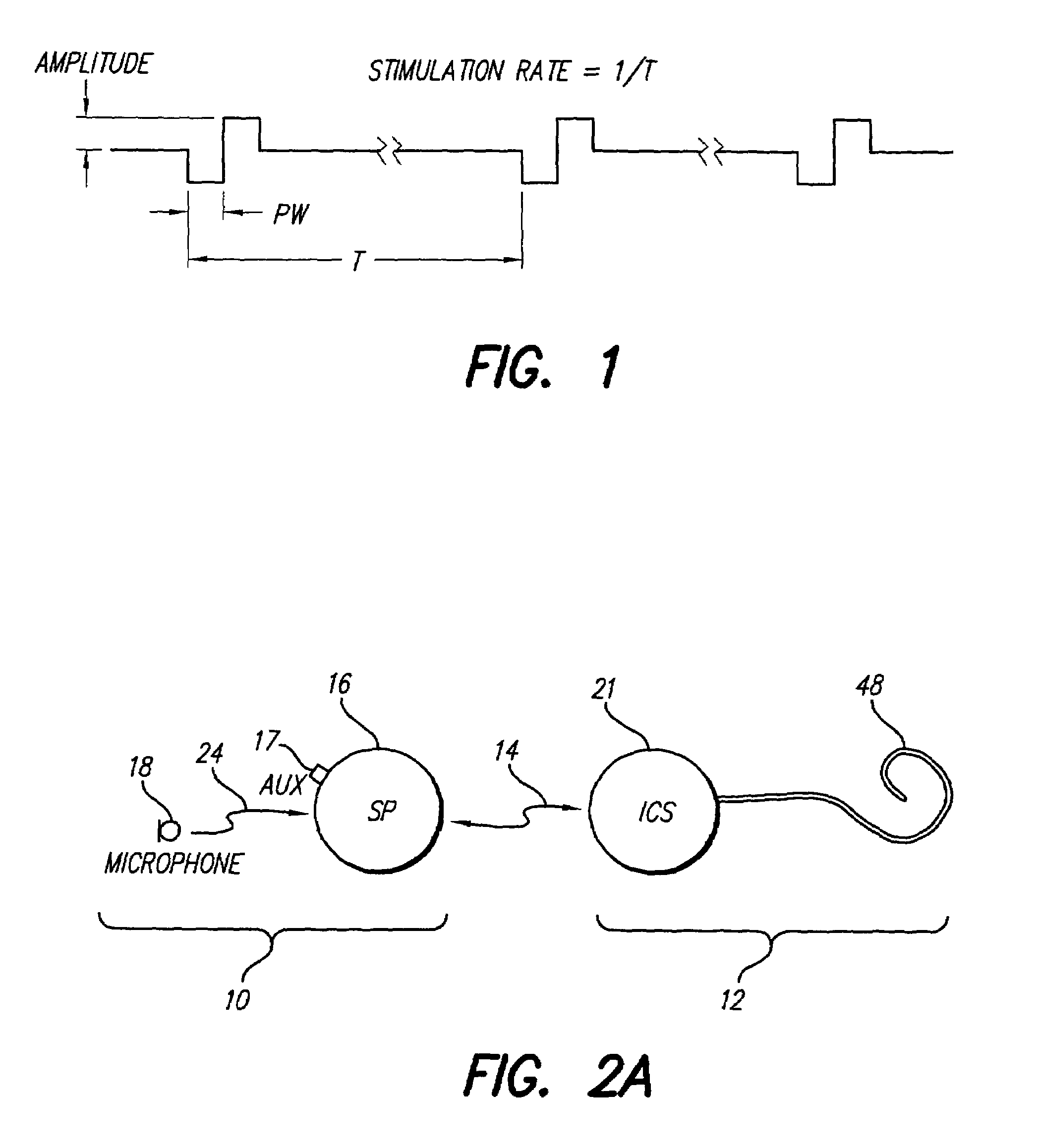
[0025]FIG. 1 shows a waveform diagram of a biphasic pulse train, and defines stimulation rate, pulse width and pulse amplitude as those terms are used in the present application.

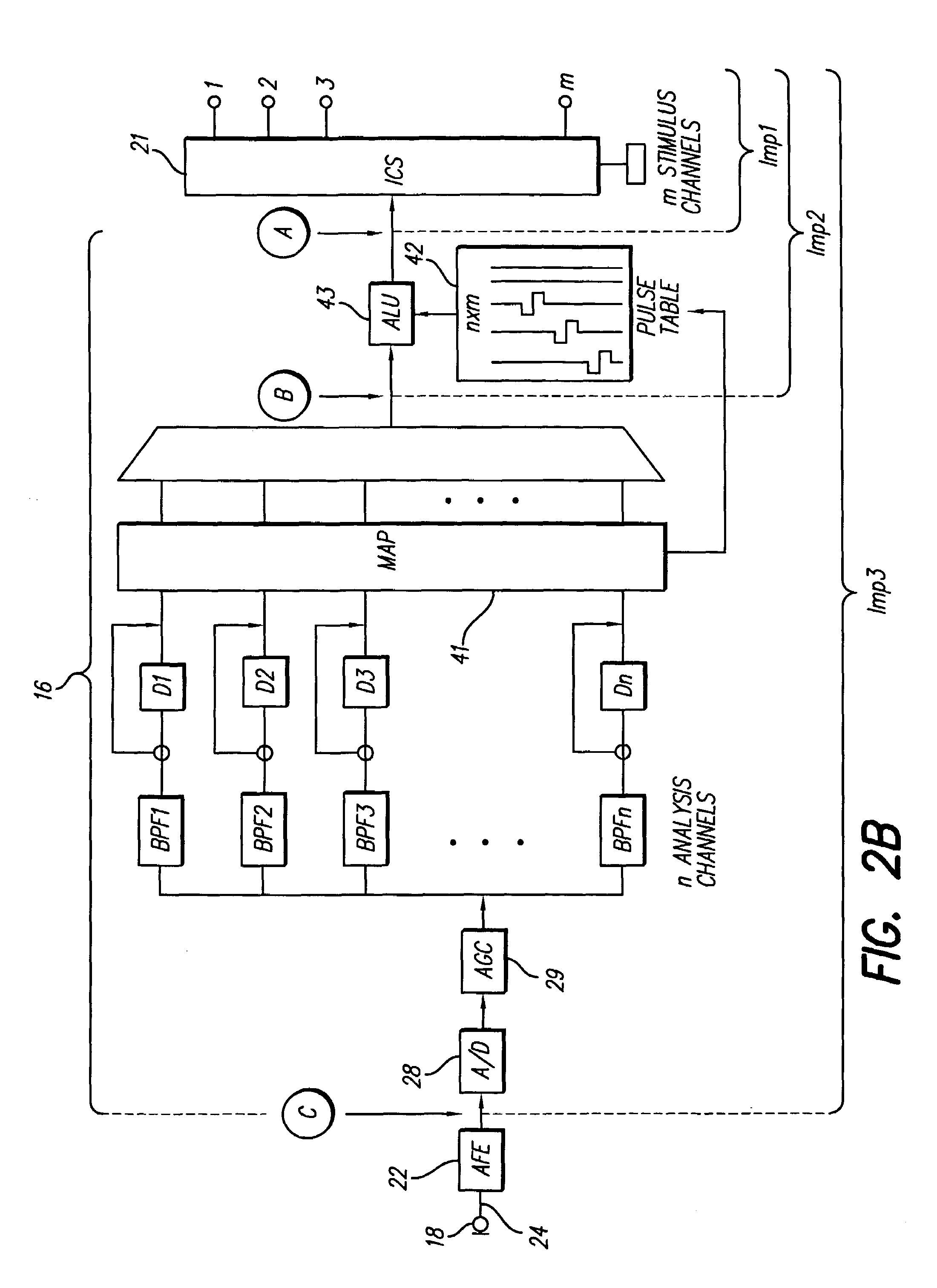
[0026]FIG. 2A shows a bionic ear cochlear stimulation system that includes a speech processor portion 10 and a cochlear stimulation portion 12. The speech processor portion 10 includes a speech processor (SP) 16 and a microphone 18. The microphone 18 may be connected directly to the SP 16, or may be coupled to the SP 16 through an appropriate communication link 24. The cochlear stimulation portion 12 includes an implantable cochlear stimulator (ICS) 21, and an electrode array 48. The...


PUM


Abstract

A cochlear implant system, or other neural stimulation system, has the capability to stimulate fast enough to induce stochastic neural firing so as to restore “spontaneous” neural activity. The stimulation rate applied to the more distally-located electrodes of an electrode array connected to the implant system is reduced from the stimulation rate applied to the more proximally-located electrodes. Thus, in the case of a cochlear implant system, the apically-located regions within the cochlea are stimulated at a reduced rate in order to conserve power. Pulse widths of the reduced-rate pulses may further be increased, and amplitudes reduced, to further conserve power. As needed, a low-level random conditioner stimulation signal may be applied to the apical regions of the cochlea in order to ensure the occurrence of random neural firings.

Description

[0001]The present application claims the benefit of U.S. Provisional Patent Application Ser. No. 60 / 466,595, filed 29 Apr. 2003, which application is incorporated herein by reference.BACKGROUND OF THE INVENTION[0002]The present invention relates to implantable neural stimulators, such as a cochlear implant, and more particularly to an implantable neural stimulator wherein the bandwidth necessary for forward telemetry is reduced through the use of spatial decimation.[0003]While the present invention relates to implantable neural stimulators, it will be described by way of example with reference to a cochlear implant, which represents one type of implantable neural stimulator. The principles of the present invention may be readily applied by those of skill in the art to all types of implantable neural stimulators. Hence, the invention is not limited to a cochlear implant.[0004]Electrical stimulation of predetermined locations within the cochlea of the human ear through an intra-cochle...

Claims


Application Information

Patent Timeline
Patent Type & Authority Patents(United States)
IPC IPC(8): A61N1/36
CPCA61N1/36032A61N1/36038
Inventor HARRISON, WILLIAM VANBROOKSFALTYS, MICHAEL A.
Owner ADVANCED BIONICS AG
Learn More