Coupling apparatus

a technology for coupling apparatus and pipe fittings, which is applied in the direction of hose connection, sleeve/socket joint, and fluid pressure sealing joint, etc. it can solve the problems of high uncertainty in predicting the completed length of piping, possible damage including thread stripping, and troublesome use, so as to improve the accuracy of predicting the length of piping assemblies, facilitate manipulable coupling, and economic

Active Publication Date: 2006-05-09
PARKER HARPER MFG
View PDF7 Cites 47 Cited by
  • Summary
  • Abstract
  • Description
  • Claims
  • Application Information

AI Technical Summary

Benefits of technology

[0014]Yet another object of the present invention is to provide the alternative coupling device with a consistent overlap at the interface between the pipe and fittings, in order that the length of piping assemblies can be more accurately predicted.
[0015]A still further object of the present invention is to provide an easily manipulatable coupling mechanism for attaching pipe and fittings which is economically manufactured and cost effective.

Problems solved by technology

Although this method of construction provides a strong mechanical connection and one that can be made leak-tight, it has shortcomings that make its use troublesome in certain situations.
The high degree of uncertainty in predicting the completed length of piping assemblies poses a serious problem in situations wherein a piping a subassembly must meet mating connections at fixed positions within a piping system.
A further problem is encountered when a taper thread fitting, for instance a valve, is to be assembled into a piping system so that the stem will reside in a certain position when the assembly is completed.
Unfortunately, with conventional taper threaded pipe and fittings, the coincidence of full pipe “makeup” and proper positioning is entirely happenstance.
Fittings are customarily over-tightened in an effort to achieve a desired orientation, resulting in possible damage including stripping of the threads.
Under-tightening invites leakage and inadvertent repositioning (usually loosening) of the fitting through normal use.
Application of the necessary torque can be detrimental to other components of the system that must provide a reaction to oppose the applied torque.
Furthermore, applying this torque requires use of large tools that are difficult to maneuver in confined areas.
In certain cases where thin walled pipe could be used, for example in relative lower pressure systems, a heavier gauge, and more expensive, pipe must be used solely for the purpose of supporting the thread cutting.

Method used


Image

  • Coupling apparatus
  • Coupling apparatus
  • Coupling apparatus

Examples


Embodiment Construction

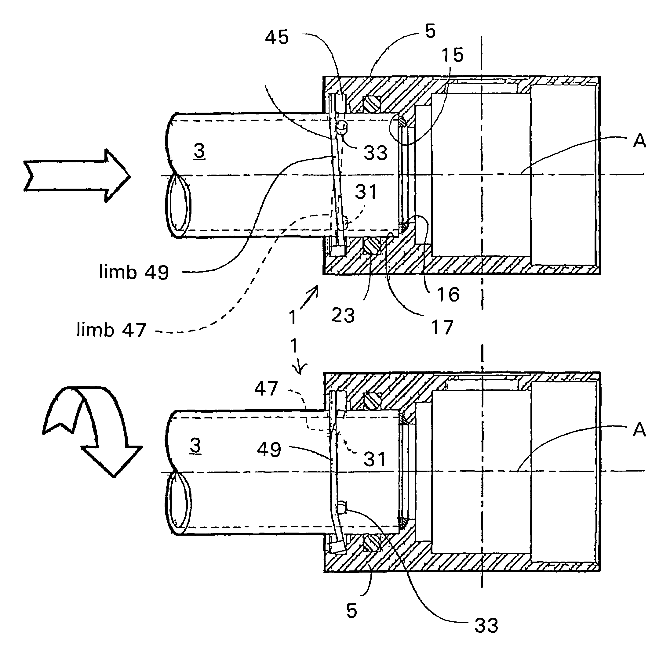
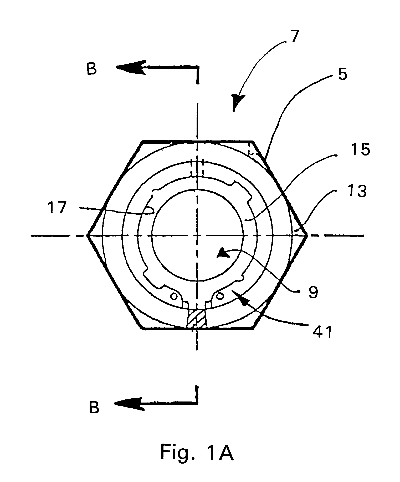
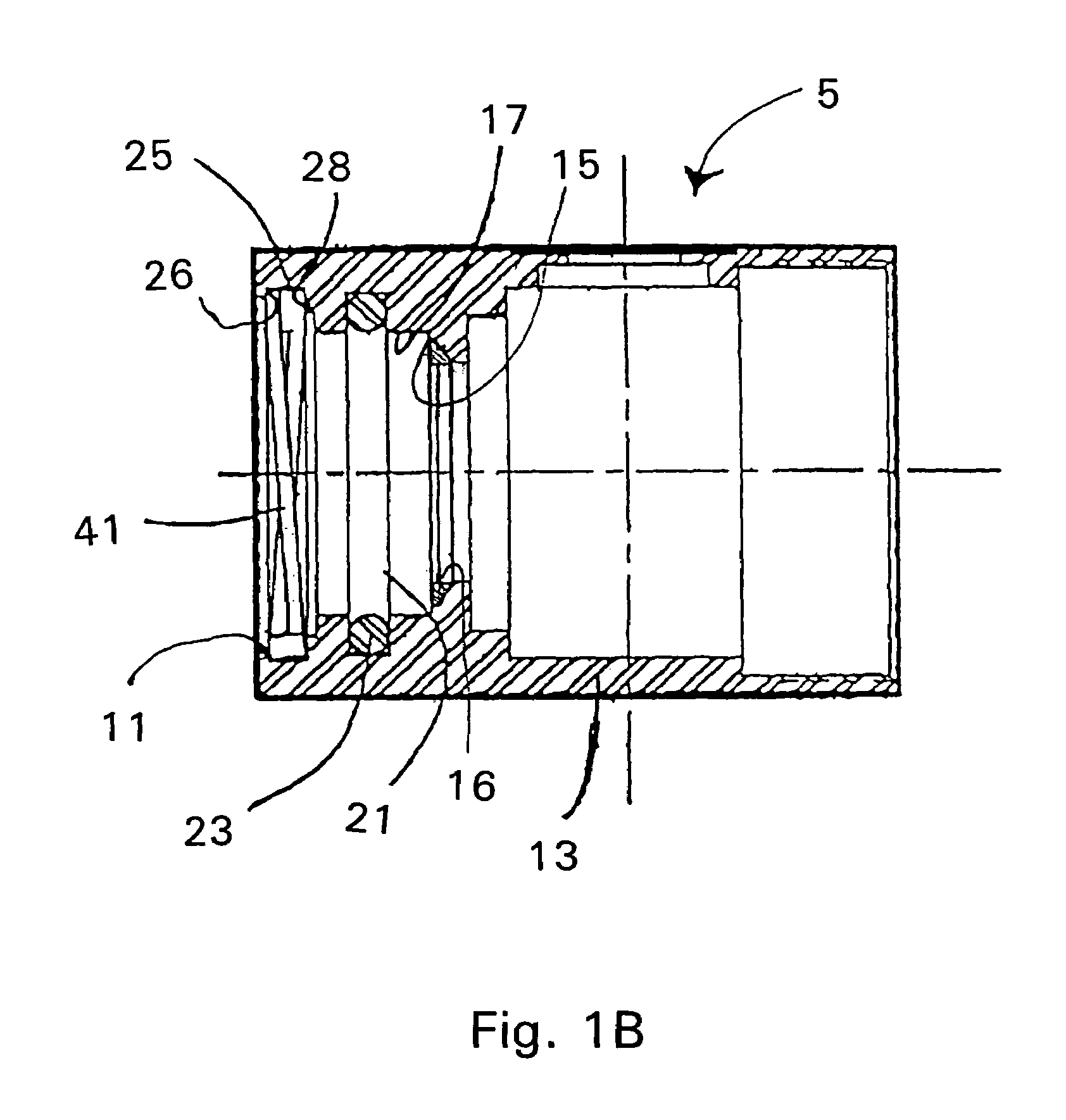
[0033]FIGS. 1A, 1B and 2A and 2B illustrate the female and male elements 7, 27 of the coupling apparatus 1, respectively. As is generally known in the art, in order to join a length of pipe or tubing, such as a tee, coupling, elbow or a valve body, it is necessary to provide one end of a pipe or tube with a male element, while providing the opposing end of a fitting, with a respective female element. Thus, by way of example, in order to join or couple a pipe and a tee, elbow, coupling or valve body together, the male element 27 of a pipe or tube 3 is connected with the female element 7 of a fitting, such as a coupling, tee, elbow or valve body 13.

[0034]In most cases a single length of pipe or tubing supports a male element 27 disposed on either end, to mate with female elements of a fitting. As this aspect of pipe fitting and design is relatively conventional in the art, and further realizing that the respective male and female parts of the coupling to be described in detail below c...


PUM


Abstract

The present invention relates to an alternative pipe coupling apparatus, to conventional tapered screw threads usually used to join ends of pipe sections to fixtures. The invention utilizes a bayonet style interlocking arrangement having a male element and a female element which join together and are opposingly biased against one another by a spring-like retaining ring to ensure an appropriate rigid and leak-proof connection between two elements.

Description

FIELD OF THE INVENTION[0001]The present invention relates to an apparatus for pipe fitting which prevents leakage and ensures a rigid connection between either a section of pipe and a fitting, for example a valve body, or even between separate pipe sections themselves. More specifically the present invention relates to an alternative to conventional tapered screw threads usually used to join ends of pipe sections to fittings and, in particular, a bayonet style interlocking arrangement having a male element and a female element which join together and are opposingly biased against one another by a spring-like retaining ring to ensure an appropriate rigid and leak-proof connection between two elements.BACKGROUND OF THE INVENTION[0002]The use of taper-threaded pipe and fittings is standard practice in the construction of small diameter (generally, ¼ inch through 2 inch) piping systems. The tapered screw thread gives rise, as the joint is tightened, to interference between the pipe and ...

Claims


Application Information

Patent Timeline
Patent Type & Authority Patents(United States)
IPC IPC(8): F16L17/00F16L37/088
CPCF16L37/248Y10S285/902
Inventor MADDEN, KENNETH
Owner PARKER HARPER MFG
Why Eureka
Try Eureka