Induction heater for cooking

Inactive Publication Date: 2006-05-09
PANASONIC CORP
View PDF9 Cites 32 Cited by
  • Summary
  • Abstract
  • Description
  • Claims
  • Application Information

AI Technical Summary

Benefits of technology

[0101]Two systems of light sources can be alternately lit up. Since one of the systems is always lit up, this structure provides the sense of safety. When different colors are used for different systems, visual recognition can be improved. When the systems are not alternately lit up, a malfunction can be easily recognized. At least three systems of light sources can be provided such th

Problems solved by technology

Therefore, there is a problem in that the user cannot easily recognize the heating state visually, unlike with a gas cooking device generating a flame or an electric heater in which the heating section is heated red.
Therefore, it is difficult for the user to visually recognize the heating state.
The induction-heating cooking device, which outputs invisible alternate magnetic fluxes, has a specific problem of being difficult to handle since it is difficult for the user to visually recognize the heating state, unlike with a gas cooking device generating a visible flame.
With induction-heating cooking devices, the user cannot visually recognize the heating state.
However, the on/off state of the power has not been much considered.
However, the power display section is small and far from the heating section for heating the cooking container.
Thus, it is troublesome to check from time to time when the user is busy or continuously cooking.
Even if the heating sections have different outputs, the difference cannot be represented with an induction-heating cooking device.
When the heating sections have different outputs, a wrong selection of the

Method used


Image

  • Induction heater for cooking
  • Induction heater for cooking
  • Induction heater for cooking

Examples


Example

EXAMPLE 1

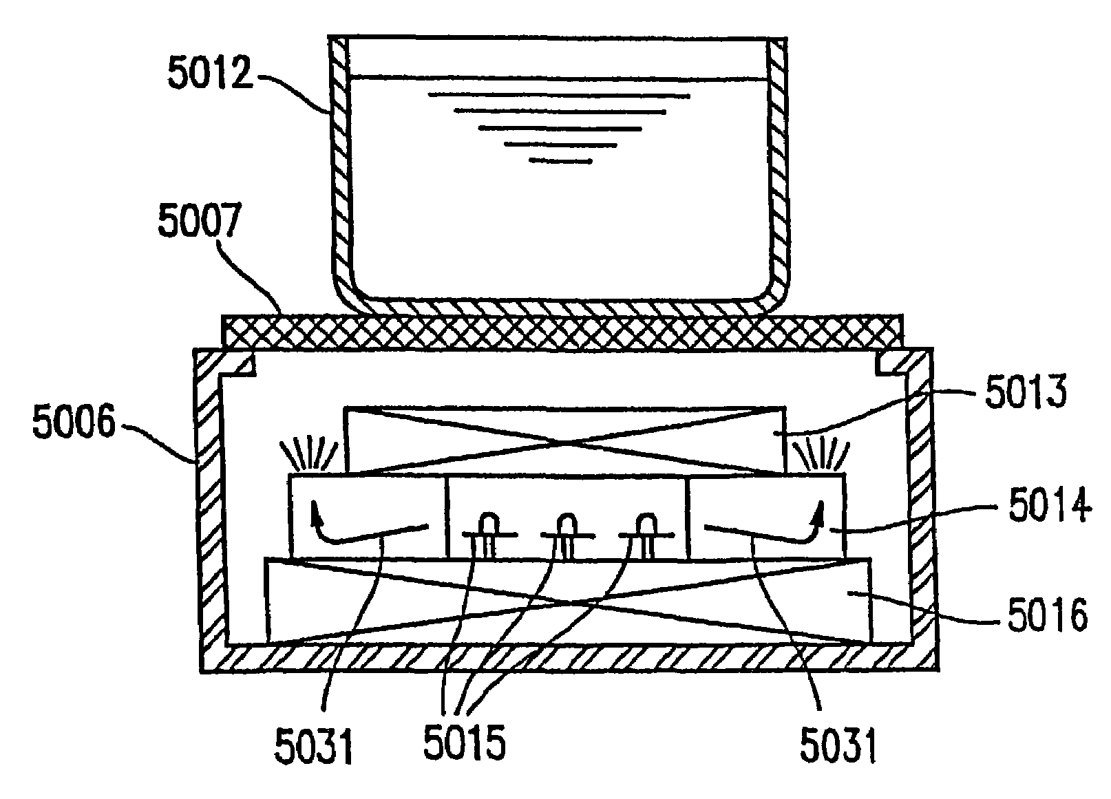
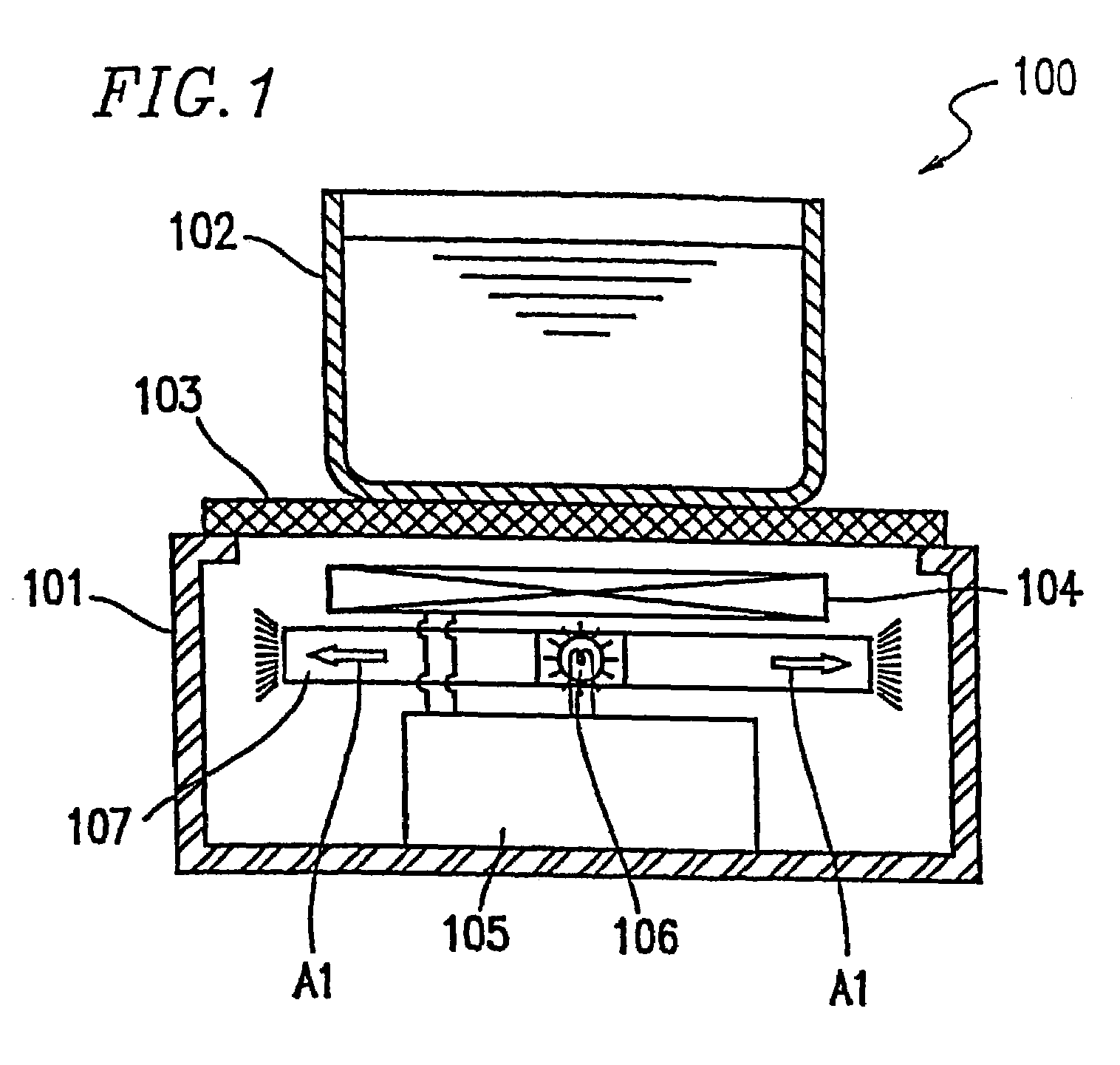
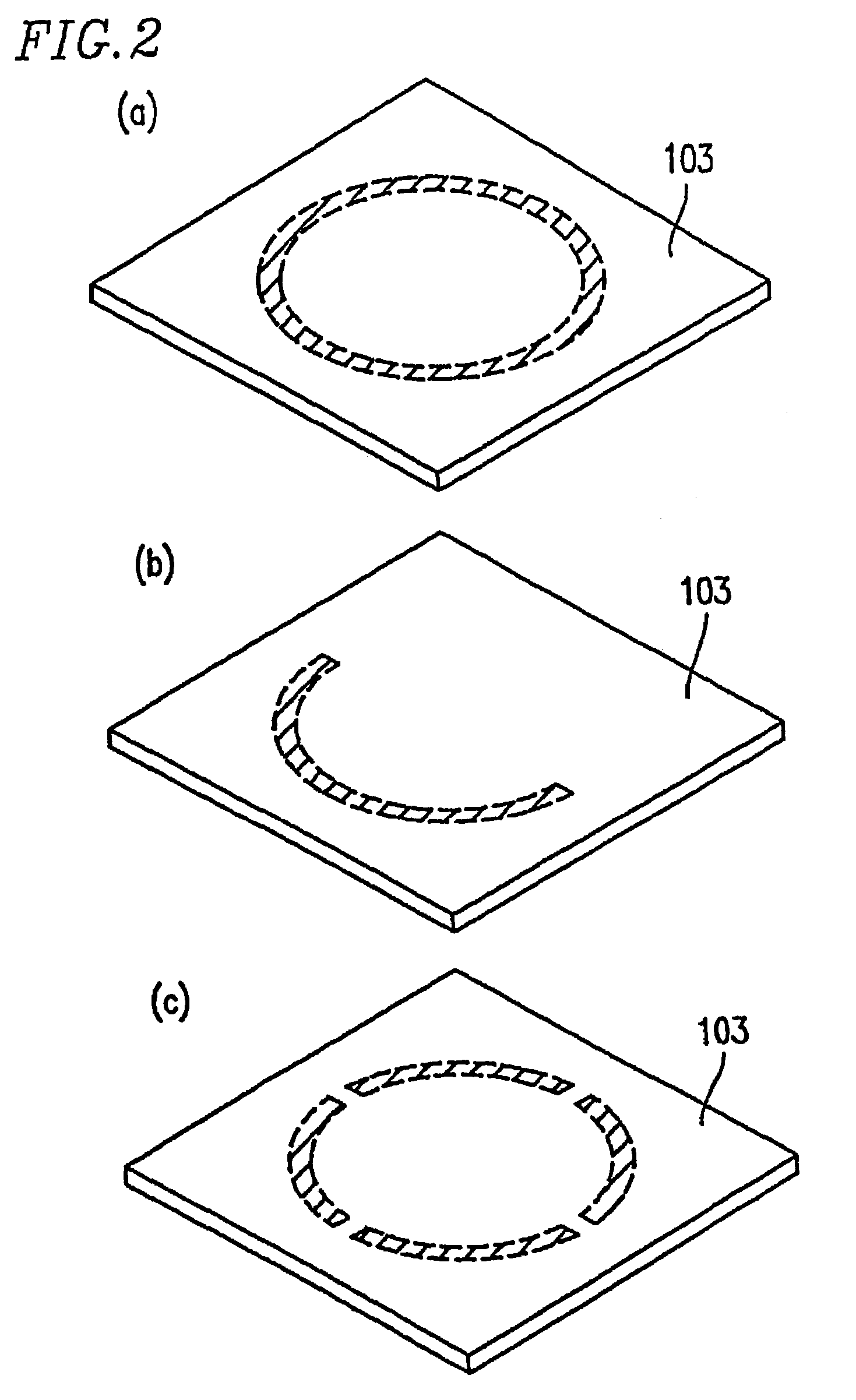
[0151]Hereinafter, a first example of the present invention will be described with reference to FIGS. 1 through 7. FIG. 1 is a schematic view of an induction-heating cooking device 100 according to the first example of the present invention. The induction-heating cooking device 100 includes a case 101 forming a main body, a cooking board 103 formed of light-transmissive, heat-resistant glass or the like, on which a cooking container 102 to be heated is to be placed, a heating coil 104 located below the cooking board 103 for heating the cooking container 102, output control means 105 for controlling an output to the heating coil 104, light emitting means 106 located below the heating coil 104 and formed of a light bulb, a semiconductor device or the like for emitting a light beam, and light conducting means 107 located below the heating coil 104 and formed of light-transmissive glass, resin or the like for allowing the light beam from the light emitting means 106 to propagat...

Example

EXAMPLE 2

[0174]With reference to FIGS. 8(a), 8(b), 9(a) and 9(b), a second example of the present invention will be described. FIG. 8(a) is a schematic view of an induction-heating cooking device 800 according to the second example of the present invention. The induction-heating cooking device 800 includes a case 201 forming a main body, a cooking board 203 formed of light-transmissive, heat-resistant glass or the like, on which a cooking container 202 to be heated is to be placed, a heating coil 204 located below the cooking board 203 for heating the cooking container 202, light emitting means 206 located below the heating coil 204 and formed of a light bulb, a semiconductor device or the like for emitting a light beam, and light conducting means 207 located below the heating coil 204 and formed of light-transmissive glass, resin or the like for allowing the light beam from the light emitting means 206 to propagate therethrough. FIG. 8(b) is a partially enlarged view of the light c...

Example

EXAMPLE 3

[0178]With reference to FIGS. 10, 11 and 12, a third example of the present invention will be described.

[0179]FIG. 10 is a schematic view of an induction-heating cooking device 1000 according to the third example of the present invention. The induction-heating cooking device 1000 includes a case 301 forming a main body, a cooking board 303 formed of light-transmissive, heat-resistant glass or the like, on which a cooking container 302 to be heated is to be placed, a heating coil 304 located below the cooking board 303 for heating the cooking container 302, a coil base 311 formed of a heat-resistant resin or the like, on which the heating coil 304 is to be placed, light emitting means 306 located below the heating coil 304 and formed of a light bulb, a semiconductor device or the like for emitting a light beam, and light conducting means 307 located below the heating coil 304 and formed of light-transmissive glass, resin or the like for allowing the light beam from the light...


PUM


Abstract

An induction-heating cooking device includes a light-transmissive cooking board on which a cooking container to be heated is to be placed; a heating coil for heating the cooking container; light emission means for emitting a light beam; and light-transmissive light conducting means for allowing the light beam emitted by the light emission means to be propagated therethrough. The light beam lights up an outer peripheral portion of the light conducting means.

Description

TECHNICAL FIELD[0001]The present invention relates to an induction-heating cooking device used in general households.BACKGROUND ART[0002]Recently, an induction-heating cooking device is a target of attention as a safe heating cooking device. Conventionally, this type of induction-heating cooking device generally represents its heating state with a display section, which is provided in the vicinity of an output setting section and lit up with, for example, a light bulb or a semiconductor device. Some built-in type induction-heating cooking devices, in which the output setting section and the cooking section are visually separated from each other, have another similar display section on a front part of the cooking section. Hereinafter, a structure of a conventional induction-heating cooking device 3600 will be described with reference to FIG. 36.[0003]As shown in FIG. 36, the induction-heating cooking device 3600 includes a case 6001 forming a main body, a cooking board 6003 on which ...

Claims


Application Information

Patent Timeline
IPC IPC(8): H05B6/12
CPCH05B6/1218H05B6/1263Y02B40/123H05B2206/022Y02B40/00H05B6/12
Inventor AIHARA, KATSUYUKINAKAKURA, HIROFUMIOKADA, KAZUICHIHOSOI, KOUICHIOONISHI, SHIGEZOU
Owner PANASONIC CORP
Why Eureka
Try Eureka