Imaging element for electronic endoscopes and electronic endoscope equipped with the imaging element

a technology of imaging element and electronic endoscope, which is applied in the field of imaging element for electronic endoscope and electronic endoscope equipped with imaging element, can solve the problems of large enlarged significant amount of time and labor required for assembling electronic endoscope, etc., and achieves the effect of reducing the diameter of electronic endoscope and facilitating and reliably carrying out positioning operation

Inactive Publication Date: 2006-05-09
HOYA CORP
View PDF6 Cites 69 Cited by
  • Summary
  • Abstract
  • Description
  • Claims
  • Application Information

AI Technical Summary

Benefits of technology

[0017]Therefore, it is an object of the present invention to provide an imaging element for electronic endoscopes of which positioning operation can be easily and reliably carried out and which makes it possible to reduce the diameter of the electronic endoscope.
[0019]By using the imaging element having the structure described above, it becomes possible to position the imaging element with respect to an imaging optical system without providing any adjustment spacer (centering means) outside the imaging element (i.e., between the imaging element and the frame member). In other words, it becomes possible to align the center of the imaging optical system (i.e., the center of the base or the intersection point between the optical axis O of the imaging optical system and the light-receiving surface) with the center of the effective region without providing any adjustment spacer. Therefore, the diameter of the main body of an endoscope can be made small, and the number of parts can be reduced.
[0020]Further, when this invention is applied to the main body of an endoscope for medical use, the reduced diameter of the main body of the endoscope makes it possible to reduce the burden of a patient. Furthermore, since it is not necessary to perform eccentric adjustment (alignment adjustment) during the assembly process of the main body of the endoscope, the assembly of the main body of the endoscope can be carried out easily and quickly as compared with the case where such eccentric adjustment is performed.

Problems solved by technology

However, such centering adjustment operations are difficult to carry out automatically, and therefore a significant amount of time and labor is required for assembling the electronic endoscope.
Further, because the spacer has to be provided outside the imaging element 100, the additional space for housing such spacer is needed inside the tip portion of the electronic endoscope, which results in a problem in that the diameter of the electronic endoscope is enlarged to such an extent.

Method used


Image

  • Imaging element for electronic endoscopes and electronic endoscope equipped with the imaging element
  • Imaging element for electronic endoscopes and electronic endoscope equipped with the imaging element
  • Imaging element for electronic endoscopes and electronic endoscope equipped with the imaging element

Examples


second embodiment

[0125]Hereinbelow, the imaging element for the electronic endoscopes of the present invention will be described.

[0126]In the endoscope equipped with the imaging element of the second embodiment, the video process circuit 220 and the D / A converter 213, which are mounted in the housing 50 of the imaging element 5 of the first embodiment, are separated from the imaging element 5, and they are disposed in the connection part 26 near the light source device 8 of the endoscope.

first embodiment

[0127]In the following description, with regard to the common features with the first embodiment mentioned above, explanation is omitted, and only the main differences are explained.

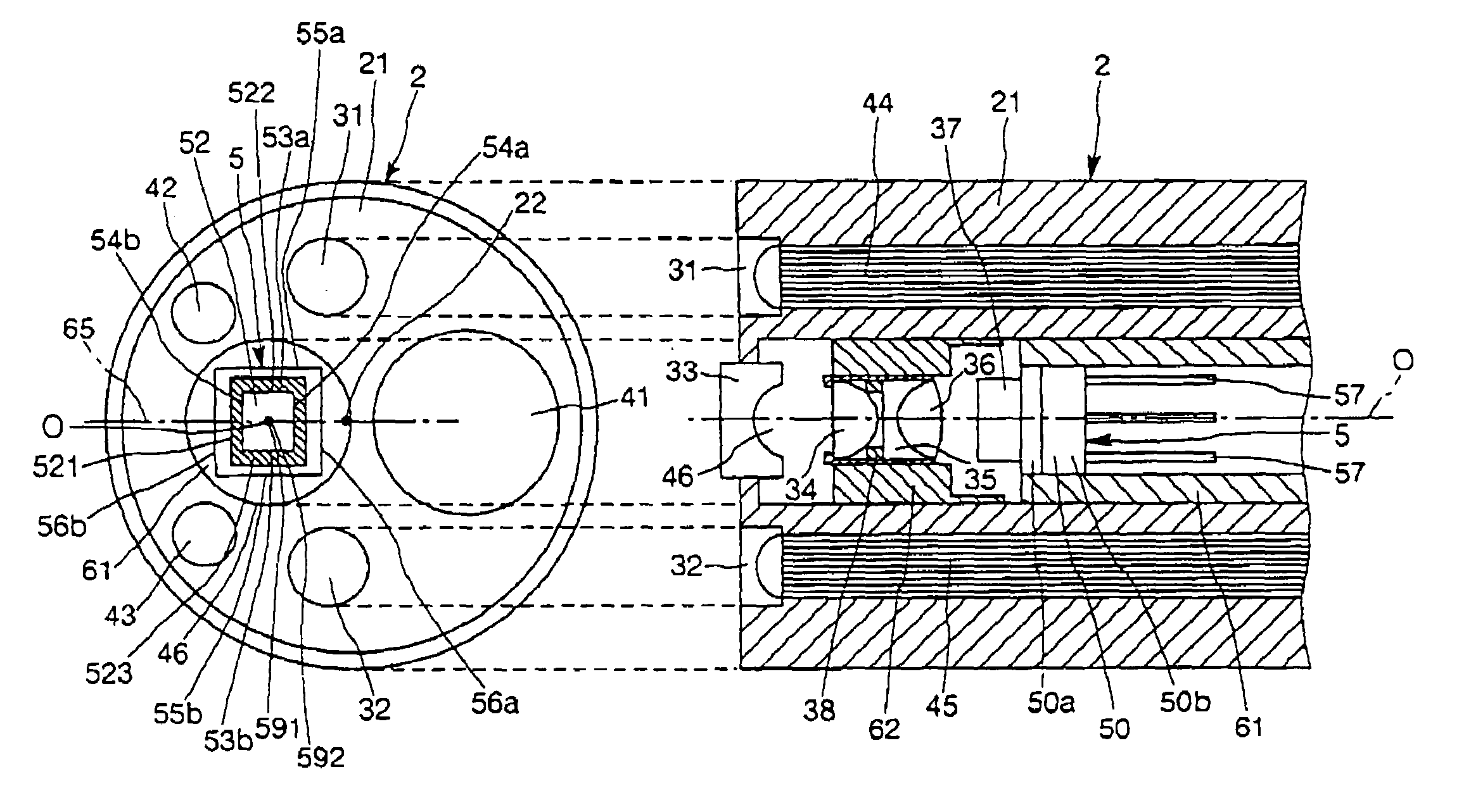
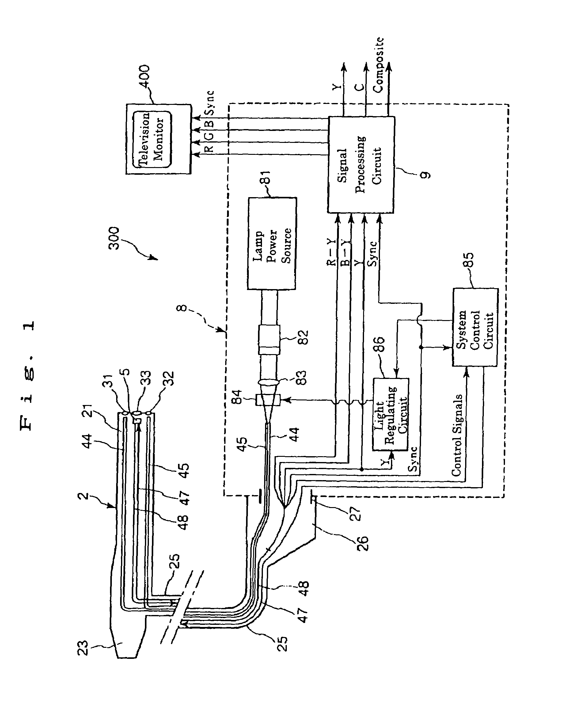
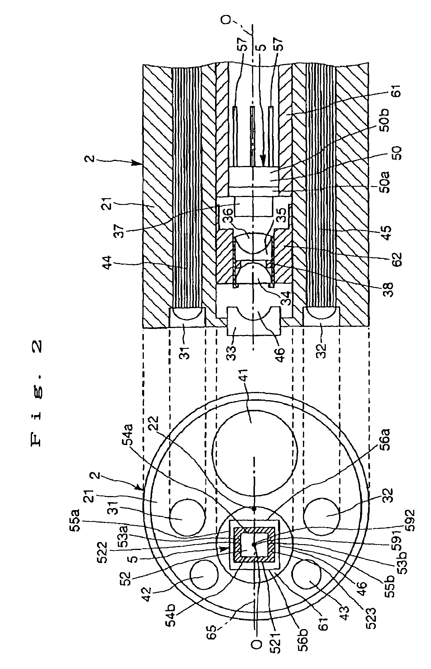
[0128]FIG. 6 is a block diagram which generally shows an electronic endoscope system provided with an electronic endoscope having an imaging element of the second embodiment according to the present invention and a light source device connected to the electronic endoscope; FIG. 7 is a plan view which schematically shows the structure of the second embodiment of the imaging element according to the present invention; FIG. 8 is a block diagram of the signal processing circuit of the endoscope shown in FIG. 6; and FIG. 9 is a block diagram of the signal processing circuit of the light source device of the electronic endoscope system shown in FIG. 6. In this connection, it is to be noted that a part of signal lines is omitted in each figure showing the circuit configuration.

[0129]As shown in FIG. 7, the sign...


PUM


Abstract

An imaging element for an electronic endoscope is disclosed. The electronic endoscope has an elongated tubular main body. At the tip end portion of the main body, there are provided an optical imaging system comprising a convex lens, a concave lens and an optical low-pass filter, a CMOS type imaging element having a CMOS sensor, and a pair of light distribution lenses. The imaging element includes the CMOS sensor, a signal processing circuit for processing a signal outputted from the CMOS sensor, and a signal control circuit for timing control for extracting a signal from the CMOS sensor. In this imaging element, the signal processing circuit and the signal control circuit are arranged along the periphery of the light-receiving surface of the CMOS sensor so that a center of the base of the sensor on the light-receiving surface is substantially aligned with a center of an effective imaging region of the image sensor.

Description

BACKGROUND OF THE INVENTION[0001]1. Field of the Invention[0002]The present invention relates to an imaging element for electronic endoscopes and an electronic endoscope equipped with the imaging element.[0003]2. Description of the Related Art[0004]In the field of medicine, electronic endoscope systems are used as diagnostic systems for examining internal sites of the human body.[0005]In general, such an electronic endoscope system includes a light source device and an endoscope which is removably mounted (connected) to the light source device. The end scope is provided with a CCD imaging sensor (imaging element) and an imaging optical system which are provided at the tip end portion thereof.[0006]As the imaging element, an imaging element is equipped with a CMOS (Complementary Metal Oxide Semiconductor) sensor (hereinafter, referred to as “CMOS type imaging element”) attracts attention.[0007]This CMOS type imaging element has various advantages. For example, in the case of the CMOS...

Claims


Application Information

Patent Timeline
Patent Type & Authority Patents(United States)
IPC IPC(8): A62B1/04A61B1/04G02B23/24A61B1/045A61B1/05G02B23/26H04N5/225H04N7/18
CPCA61B1/00096A61B1/045A61B1/05H04N5/2253H04N7/183A61B1/051H04N2005/2255H04N23/555H04N23/54
Inventor NAKASHIMA, MASAAKI
Owner HOYA CORP
Why Eureka
Try Eureka